Tutorial 4: Textures
- Part 1: Object UV Coordinates
- Part 2: Using Textures in Shaders
- Part 3: Loading Texture Data
- Part 4: Texture Filtering
- Part 5: Compressed Textures
- Part 6: Extra
- Note: Using with older OpenGL versions
Tutorial Assets: Tutorial 4 - Resources
This tutorial covers how to add textures to objects using OpenGL.
This tutorial will continue on from the last by extending the previously created code. It is assumed that you have created a copy of last tutorial’s code that can be used for the remainder of this one. For simplicity only the GGX per-fragment shader needs to be copied. The other shaders and any references to them should be removed for this tutorial (this includes the subroutines).
Part 1: Object UV Coordinates
In order to apply textures to the surface of an object there needs to be some representation of which part of a texture correspond to which part of a surface. This is done by using UV coordinates. These are 2-dimesional coordinates in the range (0,1) that are added to each point on the objects surface. These coordinates then map directly to the desired texture where the UV value of (0,0) maps to the bottom left of the texture and (1,1) maps to the top right. By using UV values in the range (0,1) the texture can be mapped irrespective of its resolution. The UV coordinates are then used just like the vertex normal by interpolating them across each polygons surface. To specify UV coordinates for a surface then the vertex information for that surface needs to be updated to add the required UV value.
- To add UV information, we need to modify the functions we previously made to generate geometry. The first thing we must do is add vertex UV data to our custom vertex type. Unlike other members of the custom vertex, UV coordinates only need 2 values so we can use a
vec2to represent them.
struct CustomVertex
{
    vec3 v3Position;
    vec3 v3Normal;
    vec2 v2UV;
};
Mapping a texture to a surface can be done in any number of ways. Take for instance a cube; this surface has 6 unique faces that can each be mapped to have the same texture cover each of them. A cube can also be mapped so that each face has a unique part of the texture applied to it or it can have any combination of unique and shared mappings.
For example, a single texture can be mapped so that several faces of the surface map to the same part of the texture. This is done by giving each vertex in those faces the same UV coordinates. For instance, given a single texture that contains data to texture 4 faces of a cube. Each of these faces is split uniformly across the texture so that the first face in the bottom left corresponds to ((0,0)-(0.5,0.5)), the second face in the bottom right corresponds to ((0.5,0)-(1,0.5)), the third face in the top left corresponds to ((0,0.5)-(0.5,1)) and the fourth face corresponds to ((0.5,0.5)-(1,1)). Each of these four faces can be mapped to a surface face by specifying the corresponding UV coordinate range to each vertex in the face. So the four vertices in a face that should map to the bottom left quad of the texture would be counter clockwise ((0,0), (0.5,0), (0.5,0.5), (0,0.5)).
- The
GL_GenerateCubefunction needs to be updated so that it creates vertex UV information. Since the required texture contains 4 parts for each face we will share 2 of those parts between 2 faces. The bottom left texture quad will map to the bottom of the cube, the lower right quad should map to the top face. The top left quad will map to the left and right face and the top right quad will map to the front and back faces.
CustomVertex VertexData[] = {
    // Create back face
      	...  	, vec2(1.0f, 1.0f) },
      	...  	, vec2 (1.0f, 0.5f) },
      	...  	, vec2 (0.5f, 0.5f) },
      	...  	, vec2 (0.5f, 1.0f) },
    // Create left face
      	...  	, vec2 (0.5f, 1.0f) },
      	... 	, vec2 (0.5f, 0.5f) },
      	...  	, vec2 (0.0f, 0.5f) },
      	...  	, vec2 (0.0f, 1.0f) },
    // Create bottom face
      	...  	, vec2 (0.5f, 0.0f) },
      	...  	, vec2 (0.5f, 0.5f) },
      	...  	, vec2 (0.0f, 0.5f) },
      	...  	, vec2 (0.0f, 0.0f) },
    // Create front face
      	...  	, vec2 (1.0f, 1.0f) },
      	...  	, vec2 (1.0f, 0.5f) },
      	...  	, vec2 (0.5f, 0.5f) },
      	...  	, vec2 (0.5f, 1.0f) },
    // Create right face
      	...  	, vec2 (0.5f, 1.0f) },
      	...  	, vec2 (0.5f, 0.5f) },
      	...  	, vec2 (0.0f, 0.5f) },
      	...  	, vec2 (0.0f, 1.0f) },
    // Create top face
      	...  	, vec2 (1.0f, 0.5f) },
      	...  	, vec2 (1.0f, 0.0f) },
      	...  	, vec2 (0.5f, 0.0f) },
      	...  	, vec2 (0.5f, 0.5f) },
};
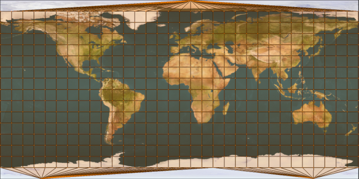
An unfortunate issue with UV mapping is what occurs at the seams of objects that map continuously around their surface. This is most evident for surfaces such as a sphere where the texture wraps completely around the surface. To the right of the seam is the texture starting at a value of ‘0’ and increasing as it moves further right. To the left of the seam are values that are approaching 1 and are decreasing as they move to the left. An issue arises as the vertices along the seam need to correspond to both values of ‘0’ and ‘1’. Leaving them as one or the other results in a duplication of the texture along the faces that share edges with the seam (for instance leaving the vertices with a value of ‘0’ will result in the faces to the left of that edge having values such as (0.9-0). Ideally they should have a value of (0.9-1) which would result in the last tenth of the texture being mapped. However now they have (0.9-0) which will map nine tenths of the texture backwards). This requires that vertices along a texture seam need to be duplicated so that they can function both as ‘0’ and ‘1’ values for the purpose of texture mapping.
- The code in
GL_GenerateSpherenow needs to be updated so that it generates vertex UV values for the sphere. Since the sphere is already built using spherical theta and phi values all we need to do to create UV coordinates is normalize these values to the range (0,1). This just requires dividing by the total range of each or the parameters respectively. Since all values are in radians this corresponds to 2π for theta and π for phi. The top and bottom vertices are just (0.5,1) and (0.5,0) respectively.
// Create vertex
p_vBuffer->v3Position = vec3(fX, fY, fZ);
p_vBuffer->v3Normal   = vec3(fX, fY, fZ);
p_vBuffer->v2UV       = vec2(1.0f - (fTheta / (float)(M_PI + M_PI)),
                        1.0f - (fPhi / (float)M_PI));
- In order to prevent issues with the way that the texture wraps around we need to duplicate the vertices along the texture seam. This requires making an additional column of vertices by increasing the number of iterations along the spheres theta direction. Since this value increments each iteration already, adding an extra loop will result in creating the new vertices with the correct UV values. This just requires increasing the loop count along the theta direction without affecting the rotation to increment each loop (dTheta). Luckily this corresponds to the order we have done things previously in the sphere function so all that needs to be done is to increment the number of ‘U’ loops after the calculation of dTheta.
// Determine required parameters
uiTessU = uiTessU + 1;
uint32_t uiNumVertices = ...
- Update the
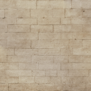
GL_GeneratePyramidfunction so that it also creates appropriate UV coordinates. Create UV mapping values based on the image to the right. These can be mapped to the faces of the pyramid however you think is best. However, to maximise texture resolution you may want to think about mapping the same texture to each of the pyramids faces. Also take care with the triangular sides of the pyramid to ensure that the brick work pattern on the texture has the correct orientation.
- Now that the data in the vertex buffer has been modified the next step is to notify OpenGL of the changed vertex buffer layout by using
glVertexAttribPointer. We now need to add a third vertex attribute for use with the new vertex UV data which we will specify at location ‘2’. Unlike previous vertex data this one only has a length of ‘2’. Update each of the previous vertex attribute calls with the required additions (remember to update all of them).
glVertexAttribPointer(2, 2, GL_FLOAT, GL_FALSE, sizeof(CustomVertex), (const GLvoid *)offsetof(CustomVertex, v2UV));
glEnableVertexAttribArray(2);
- The first step in using the new vertex UV data is to add the corresponding input to the Vertex shader code. Since we specified the vertex UV data is attribute ‘2’ it is important to make sure the corresponding layout
layout(location)qualifier matches.
layout(location = 2) in vec2 v2VertexUV;
- It should be possible to now run the program. Of course so far we haven’t done anything with the new vertex data but at the very least it is now possible to make sure that the position information hasn’t been harmed during the modifications. Running the program should result in the same output as the last tutorial.
Part 2: Using Textures in Shaders
In order to use textures in OpenGL two things must occur. The first is that the Fragment shader (when using per-fragment lighting) must have access to the UV coordinate information so that it can look up the appropriate texels (texture pixels) in the corresponding texture. This requires interpolating the UV coordinates from each vertex in a face based on the current location in the triangle that is visible. This is achieved in exactly the same way as vertex normals by relying on the OpenGL hardware to perform the interpolation.
- Update the Vertex shader so that it now outputs the UV coordinate information to the Fragment shader so it can be used during lighting calculations. To ensure it is correctly interpolated we need to specify it using
smooth. Since UV values only have 2 dimensions we specify the UV coordinate input using thevec2type. Just like in previous tutorials add the required code to themainfunction to pass the UV data from the input to the output.
layout(location = 2) smooth out vec2 v2UVOut;
//Pass-through UV coordinates
v2UVOut = v2VertexUV;
- Next you need to add the corresponding input to the Fragment shader. Since the output of the Vertex shader was specified at location ‘2’ then the corresponding input should have the same location.
layout(location = 2) in vec2 v2UVIn;
Textures in OpenGL will use GPU hardware to accelerate texture related functions. This hardware is responsible for retrieving the specified texel and any associated filtering that is required. The texture data and the settings associated with its retrieval are all incorporated into the OpenGL sampler2D object. This is specified as a uniform and as such it can be modified by the host to control various parameters of the sampler. Retrieving data from the sampler object requires using the **texture** function. This function takes as input the sampler object that encapsulates the texture data and the filtering information. It then uses this information to retrieve the appropriate value for the input UV coordinates.
- Next we will add various inputs to use textures as input in the Fragment shader. For this tutorial we will pass all material data using textures. This means we will have a texture for the diffuse colour, another texture for the specular colour and a third texture for the roughness. As a result, we no longer need the
MaterialDatauniform block that we used in the previous tutorial. This UBO and struct should be removed from the shader code as well as any references in the host code (this includes the struct declaration and UBO declarations as we no longer need the material UBOs).
Texture operations in OpenGL are performed by texture units. Each of these units has a specific texture and associated texture parameters bound to it. This unit is then responsible for that texture and any data load requests that are made against that texture. These texture units need to be linked to a shader input. This is done by setting the binding location of the corresponding input sampler2D uniform in the shader code. These inputs are set to correspond to the ID of a particular texture unit that contains the desired texture data.
- In place of the material data input from the previous tutorial we will now input the data using textures. Since each material had 3 parameters we will input these using 3 samplers. These samplers need to be added as inputs to the Fragment shader. There are many texture units in OpenGL, each of these units has a single integer number used to identify it. The first texture unit is ‘0’, the second unit is ‘1’ and so forth. For this tutorial we will set the diffuse colour sampler as using texture unit ‘0’, the specular sampler to ‘1’ and finally the roughness sampler to texture unit ‘2’ by explicitly specifying the corresponding binding locations.
layout(binding = 0) uniform sampler2D s2DiffuseTexture;
layout(binding = 1) uniform sampler2D s2SpecularTexture;
layout(binding = 2) uniform sampler2D s2RoughnessTexture;
- Next we need to add code to the
mainfunction that retrieves the appropriate data from each of the textures. Here we will use the**texture**function and pass in the UV coordinates to retrieve texture data at. By default, OpenGL stores textures in RGBA format which means that the**texture**function will returnvec4types. As we only need the first three colour channels we access them by using ‘rgb’. Since roughness is only a single float we ignore all the other 3 colour channels and only keep ‘r’.
// Get texture data
vec3 v3DiffuseColour = texture(s2DiffuseTexture, v2UVIn).rgb;
vec3 v3SpecularColour = texture(s2SpecularTexture, v2UVIn).rgb;
float fRoughness = texture(s2RoughnessTexture, v2UVIn).r;
- Previously the GGX material functions have accessed material data directly from the global UBO input. Now however the values are retrieved in the
mainfunction. As a result, you will need to update each GGX function so that the required material data is passed as an additional input to each function that requires it (Note: As we used the same variable names for both the material member variables and the loaded texture variables then this should already just work automatically).
Part 3: Loading Texture Data
Using textures within an OpenGL function is generally achieved by loading the texture from an existing file. There are many different image file formats that could be used for this task. The bitmap image file (.bmp) is one of the simplest file specifications. This can be opened and the data read by using one of SDLs inbuilt functions SDL_LoadBMP. This function can be used to load the texture and then copy it into OpenGL memory. However due to the specification of the bitmap file the coordinate mappings are different between it and OpenGL. Bitmap files are specified by placing the origin in the top left instead of the bottom left as OpenGL uses. As a result, bitmap data needs to be flipped vertically in order for it to be used in OpenGL.
- To load image data from external files we will create a new function
GL_LoadTextureBMPto handle all of this for us. This function will take as input an already created OpenGL texture ID and the filename of the texture file to load. The function will simply return true or false depending on whether the texture load succeeded.
bool GL_LoadTextureBMP( GLuint uiTexture, const char * p_cTextureFile )
{
    //*** Insert texture load code here ***
}
- Inside the load texture function we will first use the SDL function
SDL_LoadBMPto load in a bitmap file. This function returns a SDL surfaceSDL_Surfacepointer that holds the texture data as well as information about its resolution and bit depth.
// Load texture data
SDL_Surface * p_Surface = SDL_LoadBMP( p_cTextureFile );
if( p_Surface == NULL )
{
    SDL_LogCritical(SDL_LOG_CATEGORY_APPLICATION, "Failed to open texture file: %s (%s)\n", p_cTextureFile, SDL_GetError());
    return false;
}
- In order to load the texture data, we need to know what type of data was stored in the bitmap. This is because bitmaps can store 32bit RGBA data, 24bit RGB data or 8bit monochrome data. Many bitmaps also store colour data in BGR format which requires detecting and conversion. To load data into OpenGL we need the format of the data that we are loading from which we will store in a variable called
Format. We also need the format that we wish the data to be stored in when copied inside OpenGL which we will store in a variable callediInternalFormat. Most formats are either 24 or 32 bit. Since OpenGL likes rounded values we will convert 24bit to 32bit by specifying an OpenGL format of RGBA. To support loading monochrome images (which we will use for roughness) we also support single channel images or just ‘R’.
// Determine image format
GLenum Format;
GLint iInternalFormat;
if( p_Surface->format->BytesPerPixel == 4 )
{
    iInternalFormat = GL_RGBA;
    if( p_Surface->format->Rmask == 0x000000ff )
        Format = GL_RGBA;
    else
        Format = GL_BGRA;
}
else if( p_Surface->format->BytesPerPixel == 3 )
{
    iInternalFormat = GL_RGBA;
    if( p_Surface->format->Rmask == 0x000000ff )
        Format = GL_RGB;
    else
        Format = GL_BGR;
}
else if( p_Surface->format->BytesPerPixel == 1 )
{
    iInternalFormat = GL_RED;
    Format = GL_RED;
}
else
{
    SDL_LogCritical( SDL_LOG_CATEGORY_APPLICATION, "Unknown texture format: %d\n", p_Surface->format->BytesPerPixel );
    return false;
}
- Since bitmap images are flipped vertically we need rearrange the texture data so that it is oriented as expected. This requires flipping each vertical row from the top of the texture to the bottom. This is made more difficult as the size of each pixel depends on the number of bytes per pixel which can vary for each bitmap.
// Correctly flip image data
const int iRowSize = p_Surface->w * p_Surface->format->BytesPerPixel;
const int iImageSize = iRowSize * p_Surface->h;
GLubyte * p_TextureData = (GLubyte*)malloc( iImageSize );
for( int i = 0; i < p_Surface->h * iRowSize; i += iRowSize )
{
    memcpy( &p_TextureData[i], &( (GLubyte*)p_Surface->pixels )[iImageSize - i], iRowSize );
}
- Next we need to copy the texture data into the OpenGL texture. This is done by first binding the texture using
glBindTexture. This function takes as input the type of texture to bind and the texture ID to bind. In this instance we are loading a two-dimensional texture so we will use theGL_TEXTURE_2Dtype. This texture ID is passed into theGL_LoadTextureBMPfunction and is assumed to have already been created.
// Bind texture
glBindTexture(GL_TEXTURE_2D, uiTexture);
- Now we need to copy the data into the OpenGL texture. This is done using the
glTexImage2Dfunction. Since we are copying a 2D texture we specify theGL_TEXTURE_2Dbinding point, this results in the texture bound to that point usingglBindTexturebeing updated. We pass the desired internal OpenGL format usingiInternalFormatand then the resolution of the texture data by using the SDL surfaces internal width and height variables. We then specify the format of the input data using ourFormatvariable before passing the size of each input colour channel (here it is a single byte per channel) and then finally the pointer to the input texture data. All other input values need to be set to ‘0’. TheglTexImage2Dfunction will now copy data into the OpenGL texture and perform any conversions that are required in the process (this occurs in the case thatiInternalFormatis not the same asFormat). Once completed we can now free our input data buffers.
// Copy data into texture
glTexImage2D(GL_TEXTURE_2D, 0, iInternalFormat, p_Surface->w, p_Surface->h, 0, Format, GL_UNSIGNED_BYTE, p_TextureData);

// Unload the SDL surface
SDL_FreeSurface(p_Surface);
free(p_TextureData);
- The final part of the function is to initialise the texture filtering parameters for the specified texture. This is done using
glTexParameteri. For the moment we will just specify some default parameters that use the most basic texture filtering. We will do more with this later in the tutorial. This completes theGL_LoadTextureBMPfunction.
// Initialise the texture filtering values
glTexParameteri(GL_TEXTURE_2D, GL_TEXTURE_MIN_FILTER, GL_NEAREST);
glTexParameteri(GL_TEXTURE_2D, GL_TEXTURE_MAG_FILTER, GL_NEAREST); glTexParameterf(GL_TEXTURE_2D, GL_TEXTURE_MAX_ANISOTROPY_EXT, 1.0f);

return true;
- Now that we have created a function to load textures from files we need to add the host code to pass that data to OpenGL. To load texture data, we first need an OpenGL ID for each of the textures. In this tutorial we have 3 textures for each of the Diffuse colour, Specular colour and Roughness values. We then have 3 different objects (cube, sphere and pyramid) that need textures resulting in a total of 9 texture IDs.
GLuint g_uiTextures[9];
- Next we have to add code to the initialise function that creates and loads each of the textures. The first part of this is to generate the OpenGL IDs for each of the required textures. This is done using the
glGenTexturesfunction which operates like previously used OpenGL functions by taking the number of IDs to generate and a return array as input.
// Create texture uniforms
glGenTextures(9, &g_uiTextures[0]);
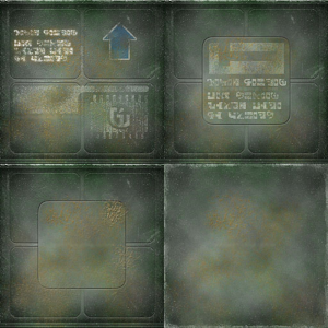
- Next we need to use out created function to load the texture data into each created texture ID. Supplied with this tutorial are the required texture files. The texture files for the cube are “CrateDiffuse”, “CrateSpecular” and “CrateRoughness” for each diffuse colour, specular colour and roughness respectively. The texture files for the sphere are “WorldDiffuse”, “WorldSpecular” and “WorldRoughness”. The texture files for the pyramid are named “PyramidDiffuse”, “PyramidSpecular” and “PyramidRoughness”.
// Load texture data
if (!GL_LoadTextureBMP(g_uiTextures[0], "Tutorial4/CrateDiffuse.bmp"))
    return false;
if (!GL_LoadTextureBMP(g_uiTextures[1], "Tutorial4/CrateSpecular.bmp"))
    return false;
if (!GL_LoadTextureBMP(g_uiTextures[2], "Tutorial4/CrateRoughness.bmp"))
    return false;
- The next step is to update the render function so that it sets the appropriate textures. Where in the previous tutorial we set the material data before each draw call we will now replace that with code to set the texture data to use. This requires 2 steps; the first is to bind a specific texture unit and set it as active. This is done using the function
glActiveTexture. In this tutorial we previously linked the diffuse sampler to use texture unit ‘0’ so this requires having the corresponding texture unit active by passingGL_TEXTURE0toglActiveTexture. Once the texture unit has been set as active we now need to bind a specific texture to it. This is done by simply using a call toglBindTextureto bind the specified texture. Similar code needs to be added before each of the other 2 draw calls to set the appropriate textures.
// Bind the textures to texture units
glActiveTexture(GL_TEXTURE0);
glBindTexture(GL_TEXTURE_2D, g_uiTextures[0]);
glActiveTexture(GL_TEXTURE1);
glBindTexture(GL_TEXTURE_2D, g_uiTextures[1]);
glActiveTexture(GL_TEXTURE2);
glBindTexture(GL_TEXTURE_2D, g_uiTextures[2]);
- Finally, you should ensure the textures are appropriately cleaned up by adding code to
GL_Quit. Cleaning up textures uses the functionglDeleteTextureswhich operates identically to other OpenGL functions that we have previously used to clean up OpenGL resources.
// Delete textures
glDeleteTextures(9, &g_uiTextures[0]);
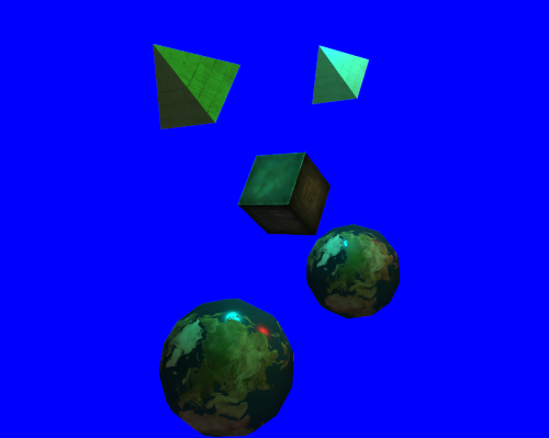
- You should now be able to compile and run your code. Assuming everything went correctly you should now have textured objects. Notice that by using texture not only does the colour vary over a surface but also the roughness. This will be most obvious with the sphere as there will only be a specular highlight over the water areas (to make things more visible you may want to change your light intensity values to white).
Part 4: Texture Filtering
OpenGL supports performing several different types of texture filtering in order to improve the quality of returned texture data. The first of these is a simple nearest neighbour filtering. This filtering we simply return the closest single texel to the requested UV input value. The second is Bilinear filtering which will interpolate between neighbouring pixels to get a smoother result. OpenGL can also use Mipmapping to generate pre-filtered textures that already have the correct Bilinear filtering applied. These mipmaps can be directly accessed to return filtered results in a single texel lookup. OpenGL can also then use Trilinear filtering which involves interpolating between different mipmap levels. Finally, OpenGL also allows for Anisotropic filtering to be added to the above filtering techniques. Anisotropic filtering can be used to improve perspective error when filtering textures.
OpenGL supports setting texture filtering for 2 different cases. These are texture minification (which occurs when multiple texels cover a single fragment) and magnification (when multiple fragments cover the same texel). Each of these different cases can have a different filtering value set. These values are set using the function glTexParameteri which allows for values to be set for the minification state GL_TEXTURE_MIN_FILTER and magnification GL_TEXTURE_MAG_FILTER.
- Previously we initialised each texture to use a basic nearest neighbour texture filter. We will now add code to change the type of filtering applied to each texture. To do this we will use key press events to change the texture filtering. We will use a key ‘1’ press to set the filtering to nearest neighbour, a ‘2’ press to use Bilinear filtering, a ‘3’ press to use Mipmapped Bilinear filtering, a ‘4’ press for Mipmapped Trilinear filtering, and a ‘5’ and ‘6’ key press for 2x and 4x anisotropic filtering respectively. To change the texture filtering parameters for a specific texture it must first be bound using
glBindTexture. Once bound we can then useglTexParameterito change the filtering values accordingly. For a key press of ‘1’ we want to use nearest neighbour. This corresponds to the OpenGL filter input ofGL_NEAREST.
// Update texture filtering
else if (Event.key.keysym.sym == SDLK_1) {
    // No filtering
    for (int i = 0; i < 9; i++) {
        glBindTexture(GL_TEXTURE_2D, g_uiTextures[i]);
        glTexParameteri(GL_TEXTURE_2D, GL_TEXTURE_MIN_FILTER, GL_NEAREST);
        glTexParameteri(GL_TEXTURE_2D, GL_TEXTURE_MAG_FILTER, GL_NEAREST);
    }
}
- Now we can add code to handle the key input ‘2’ press that will set the texture filtering to Bilinear. This has a corresponding OpenGL filter value of
GL_LINEARfor both minification and magnification.
- Mipmap filtering is much like Bilinear except it uses a filtering parameter of
GL_LINEAR_MIPMAP_NEARESTfor minification which uses the already filtered mipmaps (Note: mipmapping can only be applied to minification). This can be easily used by adding the corresponding code for a key ‘3’ press. However, to use Mipmapping we must first have mipmaps already generated that we can use. Luckily OpenGL has a function calledglGenerateMipmapthat can automatically do this for us. As we only want to do this once you’ll need to add code to the end of the texture load function that will generate the mipmaps.
// Generate mipmaps
glGenerateMipmap(GL_TEXTURE_2D);
- To use Trilinear filtering just add code for a ‘4’ key press however now use a filtering parameter of
GL_LINEAR_MIPMAP_LINEARfor minification.
- Anisotropic filtering extends whatever filtering is already set by taking multiple samples along the line of greatest perspective error. Setting anisotropic filtering can be done by using the
glTexParameterffunction and specifying the anisotropic valueGL_TEXTURE_MAX_ANISOTROPY_EXTas the one to change. Passing in a value of 1 results in no anisotropic filtering. Any larger values enable anisotropy (where 2 corresponds to 2x anisotropy etc.). Since anisotropic filtering is quite expensive it should really only be applied once Trilinear filtering has already been used. Add code to use 2x anisotropic filtering on a key ‘5’ press. For all other key presses add code to reset anisotropic filtering by settingGL_TEXTURE_MAX_ANISOTROPY_EXTto1.0f.
glBindTexture(GL_TEXTURE_2D, g_uiTextures[i]);
glTexParameteri(GL_TEXTURE_2D, GL_TEXTURE_MIN_FILTER, GL_LINEAR_MIPMAP_LINEAR);
glTexParameteri(GL_TEXTURE_2D, GL_TEXTURE_MAG_FILTER, GL_LINEAR);
glTexParameterf(GL_TEXTURE_2D, GL_TEXTURE_MAX_ANISOTROPY_EXT, 2.0f);
- Now add code for a key ‘6’ press to enable 4x anisotropic filtering. This will be identical to the code used for 2x anisotropy except
4.0fshould be passed toglTexParameterf.
- You should now be able to run your code. When viewing an object up close you should now be able to see the effects of different texture filtering parameters. Anisotropic filtering will be most obvious when looking along the top of the cube at grazing angles.
Part 5: Compressed Textures
Compressed textures provide a means of reducing memory requirements and memory bandwidth with negligible impact on performance. Modern GPUs have dedicated hardware that can perform decompression of certain texture types with similar performance to uncompressed textures. For optimal performance these textures should be stored in compressed form so they can then be directly loaded without modification. One existing file format is the .dds format which was devised as part of DirectX. This format supports all texture compression schemes mandated by DirectX and allows for texture data to be directly streamed into GPU memory without alteration. It also allows for mipmaps to be generated using a higher quality pre-process and stored directly in the file itself. However, this format uses DirectX’s convention of storing UV coordinates from top to bottom resulting in textures being flipped when loaded in OpenGL. When using compressed textures this is not easily fixed. A less known format is the .ktx format proposed as an equivalent for OpenGL. This format does not have the limitations of .dds and also allows for even more forms of texture compression.
- To support loading
.ktxtexture files you’ll need to download the libktx code.
http://www.khronos.org/opengles/sdk/tools/KTX/
- Merge the include folder with your existing directory. If compiling from source you will need to build the supplied libktx project and copy the resulting library into your existing lib directory.
- To load compressed image data from external files we will create a new function
GL_LoadTextureKTXwhich will function similarly to our existing texture load function. This function will use libktx to load the texture file so it requires the appropriate include be added.
// Using KTX import
#include <ktx.h>
bool GL_LoadTextureKTX(GLuint uiTexture, const char * p_cTextureFile)
{
    // *** Insert texture load code here ***
}
- Loading a
.ktxtexture from file is as simple as using libktx’s inbuiltktxTexture_CreateFromNamedFilefunction. This function will load the specified texture file and then copy its contents directly into the passed in OpenGL texture ID (if the ID is 0 then the function will generate a new one for you). The textures settings will be automatically set based on the properties of the input file so if the input.ktxfile uses compressed data then the appropriate settings will automatically be applied. ThektxTexture_CreateFromNamedFilefunction takes an input that is used to return a texture object that contains the relevant texture information. We can then usektxTexture_GLUploadto upload the texture into OpenGL.
// Load texture data
ktxTexture* kTexture;
KTX_error_code ktxerror = ktxTexture_CreateFromNamedFile(p_cTextureFile,
    KTX_TEXTURE_CREATE_NO_FLAGS,
    &kTexture);
if (ktxerror != KTX_SUCCESS) {
    SDL_LogCritical(SDL_LOG_CATEGORY_APPLICATION, "Failed to read texture file: %s (%s)\n", p_cTextureFile, ktxErrorString(ktxerror));
    return false;
}

// Upload texture file
GLenum GLTarget, GLError;
ktxerror = ktxTexture_GLUpload(kTexture, &uiTexture, &GLTarget, &GLError);
if (ktxerror != KTX_SUCCESS) {
    SDL_LogCritical(SDL_LOG_CATEGORY_APPLICATION, "Failed to upload texture file: %s\n", ktxErrorString(ktxerror));
    return false;
}

// Generate mipmaps
if (kTexture->numLevels == 1)
    glGenerateMipmap(GL_TEXTURE_2D);

ktxTexture_Destroy(kTexture);

// Initialise the texture filtering values
   ...
- Modify your existing code so that it uses
GL_LoadTextureKTXinstead ofGL_LoadTextureBMPto load the equivalent supplied.ktxtextures. The supplied textures use BC1 compression for diffuse and specular images and BC4 for the monochrome roughness image. You should now be able to run your program using compressed textures.
Part 6: Extra
- Notice that on the top and bottom poles of the sphere the texture has a seam where it appears to not wrap around correctly. This is due to the sphere geometry being optimised so that it has a shared top and bottom vertex. Visualising this you can see that the UV mapping is being pulled to a single point. Modify your sphere geometry generation function so that it generates the correct geometry so that the texture mapping warping is minimised at the top and the bottom of the sphere. (Hint: This requires replacing the top and bottom vertex with entire new rows of vertices with appropriate UV coordinates that reduce the UV distance between each triangle face, then modify the location of each row so that the first and last are relatively much closer to the poles which will shrink the error).
Note: Using with older OpenGL versions
This tutorial uses OpenGL functionality that is not found in older versions. For instance, the texture bindings are explicitly specified using layout(binding) which is a feature only found in OpenGL 4.2 and beyond. Similar code can still be used in older versions by allowing OpenGL host code to setup the binding locations.
This can be converted to older OpenGL versions by removing the use of layout(binding) and adding in extra host code to retrieve the OpenGL location for the uniform and using that. This is done by using glGetUniformLocation to get the location of each sampler2D uniform in the shader code. Then using glUniform1i to set the contents of that uniform to correspond to a particular texture unit. To do this the following additional host code would be needed:
// Get the uniform location and bind to texture unit
GLuint uiTextureU = glGetUniformLocation(g_uiMainProgram, "s2DiffuseTexture");
glUniform1i(uiTextureU, 0);
uiTextureU = glGetUniformLocation(g_uiMainProgram, "s2SpecularTexture");
glUniform1i(uiTextureU, 1);
uiTextureU = glGetUniformLocation(g_uiMainProgram, "s2RoughnessTexture");
glUniform1i(uiTextureU, 2);