Tutorial 6: Texture Effects
- Part 1: Emissive Materials
- Part 2: Environment Mapped Refractions
- Part 3: Planar Reflections
- Part 4: Environment Mapped Reflections
- Part 5: Extra
- Note: Optimisation
This tutorial covers how to add various texture effects such as emission, refractions and reflection.
This tutorial will continue on from the last by extending the previously created code. It is assumed that you have created a copy of last tutorial’s code that can be used for the remainder of this one.
Part 1: Emissive Materials
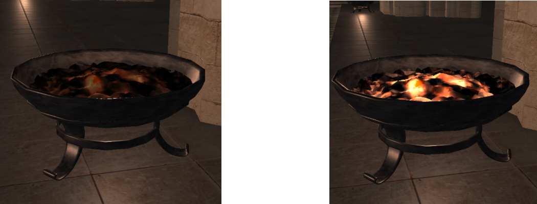
Certain types of materials not only reflect light but are also capable of emitting their own. These materials cover anything that can act as its own light source and is used to model everything from fireflies to fire embers. A material that emits its own light is called an “Emissive” material and is modelled by adding a single additional term to the lighting equation. This term simply adds the materials emissive light directly to the contribution of all other returned lighting. For simplicity it can be assumed that any material that emits light will do so with a similar surface appearance to how it reflects light. This way an emissive material can just use its diffuse texture modified by an emissive factor to determine the amount of emitted light.
- In order to support emissive materials, we must have some way of identifying them. In order to do this, we must add an additional variable to the
MaterialDataobject that holds information about a materials emissive factor. An identical value should also be added toObjectDataso that each object has a copy of its materials emissiveness.
struct MaterialData
{
    ...
    float m_fEmissive;
};
- Next, we need to add code to the Assimp material loading section within
GL_LoadScenethat will detect if an input material is emissive or not. To do this we must retrieve 2 values from Assimp’s material representation. Since the scene file we are using stores emissiveness as a multiple of the existing diffuse component we need to get both in order to determine the weighting difference between them. Once we have both we can divide the emissive value by the diffuse value to get the emissive factor.
// Check for emissive material
aiColor4D EmissiveColour(0.f, 0.f, 0.f, 0.0f);
aiGetMaterialColor(p_Scene->mMaterials[i], AI_MATKEY_COLOR_EMISSIVE, &EmissiveColour);
aiColor4D DiffuseColour(1.f, 1.f, 1.f, 1.0f);
aiGetMaterialColor(p_Scene->mMaterials[i], AI_MATKEY_COLOR_DIFFUSE, &DiffuseColour);
p_Material->m_fEmissive = EmissiveColour.r / DiffuseColour.r;
- Now we need to modify the
GL_LoadSceneNodefunction so that any new object that uses an emissive material copies the value into its own internal storage. This should be added after the existing code that copies material variables into the object’s internal storage.
p_Object->m_fEmissive = p_Material->m_fEmissive;
- In order to use an emissive material, we need to update the fragment shader code so that we can apply the emissive light as needed. To do this we will use subroutines to change between rendering with emissive or not. This will require us to create a subroutine called
Emissivethat takes the current output colour value and then modifies it by adding any required emissive light. This subroutine has 2 variants; the first simply does nothing and returns the input colour unmodified, the second will return the input colour with the additional emissive light contribution added in. Since there are no existing subroutines in the current shader code we can uselayout(index)to explicitly set the 2 subroutines to have indexes of 0 and 1 respectively. We can then set the subroutine uniform to have a fixed location of 0.
subroutine vec3 Emissive(vec3, vec3);

layout(location = 0) subroutine uniform Emissive EmissiveUniform;

layout(index = 0) subroutine(Emissive) vec3 noEmissive(vec3 v3ColourOut, vec3 v3DiffuseColour)
{
    // Return colour unmodified
    return v3ColourOut;
}

layout(index = 1) subroutine(Emissive) vec3 textureEmissive(vec3 v3ColourOut, vec3 v3DiffuseColour)
{
    // Add in emissive contribution
    return v3ColourOut + (fEmissivePower * v3DiffuseColour);
}
- The emissive subroutine uses an input uniform that corresponds to the emissive factor of the material. To use this, we must add a new input uniform to the shader. We already have a single uniform input used for the number of point lights so the new uniform is set at the next location (in this case 1).
layout(location = 1) uniform float fEmissivePower;
- In order to use the subroutines, we need to update the
mainfunction in the fragment shader so that it calls the required subroutine. This just requires adding an additional line of code at the end of the function so that the emissive contribution is added to the final colour as the last step before it is returned.
// Add in any emissive contribution
v3RetColour = EmissiveUniform(v3RetColour, v3DiffuseColour);
- Now the shader has been updated to support emissive materials we just need to update the render function so that the correct subroutine is chosen based on the current object’s material properties. Within the render function we first just need to add a list of available subroutines. Here the 2 emissive subroutines were created with indexes of ‘0’ and ‘1’.
// Initialise sub routine selectors
const GLuint uiEmissiveSubs[] = {0, 1};
- Within the object loop within the render function, we now need to select the appropriate subroutines. We can do this by creating a new subroutine array that contains the corresponding value from the list of available subroutines based on the objects emissiveness. We just pass this new array to
glUniformSubroutinesuivto setup the required subroutine. Since the materials emissive value is a power factor that can have a range of values. All we have to do is check if it is anything other than zero. If it is then we use the emissive subroutine otherwise we use the non-emissive subroutine.
// Set subroutines
GLuint uiSubRoutines[1] = {uiEmissiveSubs[p_Object->m_fEmissive != 0]};
glUniformSubroutinesuiv(GL_FRAGMENT_SHADER, 1, uiSubRoutines);
- Next, we just need to update the shader uniform with the emissive power of the current objects material if it is actually an emissive material.
// If emissive then update uniform
if (p_Object->m_fEmissive != 0.0f) {
    glUniform1f(1, p_Object->m_fEmissive);
}
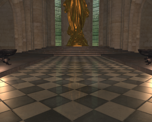
- You should now be able to run your program and see the effects of having emissive material support. For the tutorials input scene the main emissive objects are the embers in each of the braziers.
Part 2: Environment Mapped Refractions
Transparent objects can be simulated in many different ways. To simulate real world materials a transparent object should refract the light coming in from behind the surface. This refraction is based on the index of refraction for the material with respect to the index of refraction of the surrounding medium (generally this is assumed to be air). In order to support refractions, it is necessary to know the light coming in from behind an objects surface along the ideal refraction direction. This refraction direction can change with respect to the surfaces index of refraction at the visible point and the incoming view direction. To support this range of possible directions an environment map is often used. This is often represented as a cube mapped texture that completely surrounds the object in question like a big box. This box contains all the incoming light values for each position on the inside of the cube. A direction vector can then be used to determine the sample on the surface of the cube to work out the incoming light along that direction. We therefore can sample the environment map for the incoming light along any refraction direction in 3D.
- Next, we will add refraction support to our program. Normally this requires having an environment map for each transparent object. However, in our test scene the only transparent objects are the windows around the cathedral. Since all these windows look outwards, we can simply use a single environment map that surrounds the entire scene. The light coming through each window can then be sampled directly from the scenes outside environment map. To use transparency, we must add an additional variable to the
MaterialDataobject that holds whether the material is transparent. A corresponding variable should also be added to theObjectDatatype in much the same way as what was previously done for emissive materials.
struct MaterialData
{
    ...
    bool m_bTransparent;
};
- To use transparency, we need to detect any materials that have a transparent component. For our scene this is encoded in the alpha channel of the diffuse texture. We can therefore detect a transparent material by checking which materials have a diffuse texture with an alpha component. We therefore need to add code near the end of the material loading section of
GL_LoadScenethat will retrieve the size of the alpha component of the already loaded diffuse texture usingglGetTexLevelParameteriv. If the size of the alpha component is not zero, then the object is transparent.
// Check for transparent material
glBindTexture(GL_TEXTURE_2D, p_Material->m_uiDiffuse);
GLint iAlpha = 0;
glGetTexLevelParameteriv(GL_TEXTURE_2D, 0, GL_TEXTURE_ALPHA_SIZE, &iAlpha);
p_Material->m_bTransparent = (iAlpha > 0);
- We will now modify our
SceneDatatype so that it contains an additional array used to store transparent objects. This will be used later as it is often desirable to treat transparent objects specially under certain circumstances.
struct SceneData
{
    ...
    ObjectData * mp_TransObjects;
    unsigned m_uiNumTransObjects;
};
- You should now add code to make sure that the transparent object list is allocated during scene load. To do this add similar code to that which was used to allocate the normal object list. For the moment we will optimistically allocate the list with the same number of elements as the normal object list. You should also add the relevant code to the scene unload function to deallocate the newly created list.
- Now we need to add code to
GL_LoadSceneNodeso that any object that uses a transparent material is loaded correctly. This code should be added after the existing code that copies across the objects material and transform properties. This code will just set the objects transparent variable and then add it to the transparent object list.
// Add to transparent object list as needed
p_Object->m_bTransparent = p_Material->m_bTransparent;
if (p_Material->m_bTransparent) {
    SceneInfo.mp_TransObjects[SceneInfo.m_uiNumTransObjects] = *p_Object;
    ++SceneInfo.m_uiNumTransObjects;
}
- In order to use a transparent material, we need to update the fragment shader code again so that we can apply the refracted light as needed. To do this we will add another subroutine to change between transparent or not. To do this we will create a subroutine called
RefractMapthat has 2 variants that function in the same way as the previously added emissive subroutines. The difference is that the transparent subroutine will calculate the refracted light amount using the functionSpecularTransmitand then blend it with the existing colour based on the materials alpha component using the inbuilt OpenGL functionmix. This is a result of transparent materials not reflecting as much light as a certain amount of it actually goes through the surface instead of reflecting. The alpha component is used to determine how much light is reflected and how much is refracted. The 2 new subroutines are created using the next available indexes (here ‘2’ and ‘3’).
subroutine vec3 RefractMap(vec3, vec3, vec3, vec4, vec3);

layout(location = 1) subroutine uniform RefractMap RefractMapUniform;

layout(index = 2) subroutine(RefractMap) vec3 noRefractMap(vec3 v3ColourOut, vec3 v3Normal, vec3 v3ViewDirection, vec4 v4DiffuseColour, vec3 v3SpecularColour)
{
    // Return colour unmodified
    return v3ColourOut;
}

layout(index = 3) subroutine(RefractMap) vec3 textureRefractMap(vec3 v3ColourOut, vec3 v3Normal, vec3 v3ViewDirection, vec4 v4DiffuseColour, vec3 v3SpecularColour)
{
    // Get specular transmittance term
    vec3 v3Transmit = SpecularTransmit(v3Normal, v3ViewDirection, v4DiffuseColour.rgb, v3SpecularColour);

    // Add in transparent contribution and blend with existing
    return mix(v3Transmit, v3ColourOut, v4DiffuseColour.w);
}
The amount of light transmitted through a surface is defined by its transmittance function. A simple shader for calculating transmitted light can be given by the specular Fresnel transmittance function. This function calculates the visible light \(L_{V}\left( \overrightarrow{\mathbf{v}} \right)\) along view direction \(\overrightarrow{\mathbf{v}}\) from a point based on the transmitted light \(E_{T}(\overrightarrow{\mathbf{t}})\) from along the ideal refraction direction \(\overrightarrow{\mathbf{t}}\) and the surfaces diffuse colour \(\rho_{d}\).
\[L_{V}\left( \overrightarrow{\mathbf{v}} \right) = \rho_{d}\frac{\eta_{o}^{2}}{\eta_{i}^{2}}(1 - F\left( \overrightarrow{\mathbf{r}}\mathbf{, -}\overrightarrow{\mathbf{n}} \right))E_{T}(\overrightarrow{\mathbf{t}})\]This requires knowing the ratio of the index of refraction between the surface of the object and the neighbouring medium. We will assume that the surface is in air so then the outgoing index of refraction \(\eta_{o}\) is just 1.0. The index of refraction for the surfaces material can be calculated from the Fresnel term \(F_{0}\) used in the GGX shader.
\[\frac{1}{\eta_{i}^{2}} = \frac{1 - \sqrt{F_{0}}}{1 + \sqrt{F_{0}}}\]- To implement the specular transmission shader, we need the incoming light from the transmittance direction. These values are stored in an environment cube map so we need to add an additional texture input to the fragment shader that will hold the environment map. Unlike previous texture inputs this needs to be of type
samplerCube. We explicitly give it the next available texture binding location (we already have 3 textures used in this tutorial so the next binding location is ‘3’).
layout(binding = 3) uniform samplerCube scRefractMapTexture;
- We can now implement the
SpecularTransmitfunction within our fragment shader. This function will take in the surface normal and view direction which it will use to calculate the refraction direction using OpenGL’s inbuiltrefractfunction. It will then implement the above specular transmission equation using the input diffuse and specular textures. The transmitted light is read from the cube map texture which is accessed by passing a direction vector. The texture function will automatically sample the environment map as required based on this normalized direction vector. Here we use the refraction direction to get the correct environment map value.
vec3 SpecularTransmit(in vec3 v3Normal, in vec3 v3ViewDirection, in vec3 v3DiffuseColour, in vec3 v3SpecularColour)
{
    // Calculate index of refraction from Fresnel term
    float fRootF0 = sqrt(v3SpecularColour.x);
    float fIOR = (1.0f - fRootF0) / (1.0f + fRootF0);

    // Get refraction direction
    vec3 v3Refract = refract(-v3ViewDirection, v3Normal, fIOR);

    // Get refraction map data
    vec3 v3RefractColour = texture(scRefractMapTexture, v3Refract).rgb;

    // Evaluate specular transmittance
    vec3 v3RetColour = fIOR * (1.0f - schlickFresnel(v3Refract, -v3Normal, v3SpecularColour));
    v3RetColour *= v3DiffuseColour;

    // Combine with incoming light value
    v3RetColour *= v3RefractColour;

    return v3RetColour;
}
- To use the new subroutine, we need to add code to the main function to call the required function. This should be added after the existing ambient contribution is applied but before the emissive contribution.
// Add in any refraction contribution
v3RetColour = RefractMapUniform(v3RetColour, v3Normal, v3ViewDirection, v4DiffuseColour, v3SpecularColour);
- Unlike previously we now need the diffuse colour term to have four components. This is because we are now checking the fourth alpha channel to see if the texture is transparent. This requires modifying the existing diffuse texture lookup to make it return all four channels and then making a new three channel variable that can be used with existing functions.
// Get texture data
vec4 v4DiffuseColour = texture(s2DiffuseTexture, v2UVIn);
vec3 v3DiffuseColour = v4DiffuseColour.rgb;
- Now the shader is complete we need to actually load in an environment map that can be used for transparent materials. Since all the transparent materials (i.e. windows) all use the same environment map we only need to load in a single texture that can be used by all transparent objects.
GLuint g_uiSkyBox;
- We next must add code to the initialise function that will load in the cube map texture. For this tutorial one is already supplied which is called
SkyBox.ktx. We can load this texture the same as we have previously except this time, we need to load it asGL_TEXTURE_CUBE_MAPtype. Once loaded we can then bind it and set up some initial texture filtering options.
// Load SkyBox
glGenTextures(1, &g_uiSkyBox);
GL_LoadTextureKTX(g_uiSkyBox, "Cathedral/textures/SkyBox.ktx");

// Bind and set up SkyBox texture
glBindTexture(GL_TEXTURE_CUBE_MAP, g_uiSkyBox);
glTexParameteri(GL_TEXTURE_CUBE_MAP, GL_TEXTURE_MIN_FILTER, GL_LINEAR_MIPMAP_LINEAR);
glTexParameteri(GL_TEXTURE_CUBE_MAP, GL_TEXTURE_MAG_FILTER, GL_LINEAR);
glTexParameterf(GL_TEXTURE_CUBE_MAP, GL_TEXTURE_MAX_ANISOTROPY_EXT, 4);
- In the render function we now need to add a list of subroutines that correspond to using transparency or not. This list corresponds to the indexes of the refraction subroutines (in this case ‘2’ and ‘3’).
const GLuint uiRefractSubs[] = {2, 3};
- We will now modify the code that sets up the subroutines that should be used for each object. Now we need to pass in subroutine indexes for 2 different subroutines. We update the code so it now sets both the emissive and the refractive subroutine indexes based on the current object’s material properties. This should replace the existing code that selects the subroutines.
// Set subroutines
GLuint uiSubRoutines[2] = {uiEmissiveSubs[p_Object->m_fEmissive != 0],
    uiRefractSubs[p_Object->m_bTransparent]};
glUniformSubroutinesuiv(GL_FRAGMENT_SHADER, 2, uiSubRoutines);
- Lastly within the object loop of the render function we need to make sure the cube map texture is bound whenever a transparent object is detected. Since the cube map texture was explicitly set to binding location ‘3’ we must set the environment map texture to the corresponding texture binding.
// If transparent then update texture
if (p_Object->m_bTransparent) {
    glActiveTexture(GL_TEXTURE3);
    glBindTexture(GL_TEXTURE_CUBE_MAP, g_uiSkyBox);
}
- As cube maps are made from 6 different image faces, the currently set texture filtering settings only apply when sampling from each face. This can cause visible seams when looking at the edge of a cube map face. To fix this we need to tell OpenGL to filter across cube map faces. This should be added to the initialise function.
glEnable(GL_TEXTURE_CUBE_MAP_SEAMLESS);
- You should now be able to run your program and see the effects of having transparent material support. For the tutorials input scene the main transparent objects are the windows which should now allow you to see out of them.

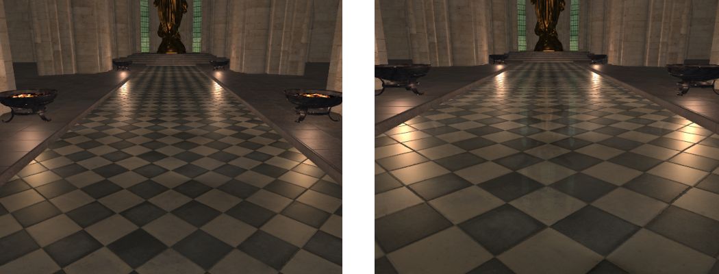
Part 3: Planar Reflections
Much like with transparent objects it is possible to simulate reflective objects in many different ways. One such way can use environment maps similar to transparencies however this technique has obvious errors when applied to planar or flat reflective surfaces. The most obvious type of real-world object like this is a simple mirror. Planar reflections require a high-quality reflection that is perfectly aligned with the corresponding reflection direction for each observed point. Since planar reflections only occur out from a single face only a single texture is needed to hold the reflection data. This special type of reflection needs to be handled specially.
- Next, we will add reflection support to our program. To use reflections, we must add an additional variable to the
MaterialDataobject that holds whether the material is reflective. This is just a simple Boolean like the previous transparency variable.
struct MaterialData
{
    ...
    bool m_bReflective;
};
- A corresponding variable should also be added to the
ObjectDatatype except this time we don’t just store a Boolean value. The material type only needs to determine if the material is reflective. The object type will instead store an integer that can be used to represent the type of reflective surface. We will use a value of ‘0’ to represent that it is not reflective and a value of ‘1’ to signal it is planar reflective. Additional reflective types will be added later. We will also add a couple of additional variables that we will use to store the reflective texture and a UBO that holds the required information to map the texture to the surface of the rendered object.
struct ObjectData
{
    ...
    unsigned m_uiReflective;
    GLuint m_uiReflect;
    GLuint m_uiReflectVPUBO;
};
- To use reflections, we need to detect any materials that have a reflective component. This can be determined by reading Assimp’s reflectivity factor for each material and checking if it’s greater than zero. We therefore need to add code near the end of the material loading section of
GL_LoadScenethat will retrieve the reflectivity factor and then update the material data’s variable as required.
// Check for reflective material
float fReflectivity = 0.0f;
aiGetMaterialFloat(p_Scene->mMaterials[i], AI_MATKEY_REFLECTIVITY, &fReflectivity);
p_Material->m_bReflective = (fReflectivity > 0.0f);
- We will now modify our
SceneDatatype so that it contains an additional array used to store reflective objects. This will be used later as reflective objects require additional handling in order to generate the reflection data. This will be far more efficient if we can find all reflective objects directly.
struct SceneData
{
    ...
    ReflectObjectData * mp_ReflecObjects;
    unsigned m_uiNumReflecObjects;
};
- The new list of reflective objects requires a new object type. This type stores additional data only required by reflective objects and only data that is not required for rendering. For the moment this type stores an index into the object list that can be used to locate the corresponding object data (Note: an index is used as opposed to a pointer as pointers become invalidated whenever memory is reallocated). For a planar reflection we need to know the values of the plane that the reflection is around. We store this by adding an additional value to the new
ReflectObjectDatatype.
struct ReflectObjectData
{
    unsigned m_uiObjectPos;
    // Reflection data
    vec4 m_v4Plane;
};
- You should now add code to make sure that the reflective object list is allocated during scene load. To do this add similar code to that which was used to allocate the normal object list. For the moment we will optimistically allocate the list with the same number of elements as the normal object list just like we did for the transparent object list. You should also add the relevant code to the scene unload function to deallocate the newly created list. Also add code to destroy the created reflection texture and UBO for any reflective object.
- Now we need to add code to
GL_LoadSceneNodeso that any object that uses a reflective material is loaded correctly. This code should be added after the existing code that copies across transparent materials. By default, we will initialise the object reflectivity to ‘0’ to correspond to no reflection. We will then check the materials reflectivity and if it is set then we will add additional code to check whether the object has a planar reflection.
// Add to reflective object list as needed
p_Object->m_uiReflective = 0;
if (p_Material->m_bReflective) {
    // *** Add object bounding box calculation here ***

    // *** Add planar object detection here ***
}
- To determine if an object is planar, we need to determine the objects bounding box. This is the smallest box that will fit around the entire object. If one of the sides of the box has zero length, then the object inside of it is a simple plane. To simplify things, we will just calculate an axis aligned bounding box (AABB) which is a simplification that assumes that each side of the box is aligned with one of the coordinate axes. For a plane this is unlikely to be true in world space as it can take any orientation but we will make the simplifying assumption that the objects model space coordinates have been created so that the surface is axis aligned. We can then determine the AABB in model space by looping over the meshes vertices and storing a running total of the minimum and maximum values along each of the coordinate axis. The final minimum and maximum will give the sides of the complete AABB.
// Calculate objects bounding box
const aiMesh * p_AIMesh = p_Scene->mMeshes[p_Node->mMeshes[i]];
vec3 v3AABBMin = vec3(FLT_MAX);
vec3 v3AABBMax = vec3(-FLT_MAX);
for (unsigned j = 0; j < p_AIMesh->mNumVertices; j++) {
    vec3 v3Vert(p_AIMesh->mVertices[j].x,
                p_AIMesh->mVertices[j].y,
                p_AIMesh->mVertices[j].z);
    v3AABBMin = min(v3AABBMin, v3Vert);
    v3AABBMax = max(v3AABBMax, v3Vert);
}
- Using the calculated bounding box, we can now check if one of the sides has near zero length (we use near zero to compensate for floating point errors in the calculation of the bounding box). If one of the sides has zero length, then the object is planar reflective and we can setup the required data.
// Check if planar or not
vec3 v3AABBSize = v3AABBMax - v3AABBMin;
if ((v3AABBSize.x < 0.00001f) || (v3AABBSize.y < 0.00001f) || (v3AABBSize.z < 0.00001f)) {
    // Set object as planar reflective
    p_Object->m_uiReflective = 1;
    ReflectObjectData * p_RObject = &SceneInfo.mp_ReflecObjects[SceneInfo.m_uiNumReflecObjects];

    // Set object position in reflective object
    p_RObject->m_uiObjectPos = SceneInfo.m_uiNumObjects;

    // *** Add reflection texture generation here ***

    // *** Add UBO generation here ***

    // *** Add object plane calculation here ***

    ++SceneInfo.m_uiNumReflecObjects;
}
- As a planar reflection requires a single texture to store the reflection image, we need to create a new one and give it some reasonable texture filtering parameters. Since we will use mipmapping (and require it in order to provide certain effects) we will ensure mipmapped filtering is enabled and that enough texture storage is allocated for every mipmap level.
// Generate texture for reflection map
glGenTextures(1, &p_Object->m_uiReflect);
glBindTexture(GL_TEXTURE_2D, p_Object->m_uiReflect);
int iLevels = (int)ceilf(log2f((float)max(g_iWindowWidth, g_iWindowHeight)));
glTexStorage2D(GL_TEXTURE_2D, iLevels, GL_RGB8, g_iWindowWidth, g_iWindowHeight);

// Initialise the texture filtering and wrap values
glTexParameteri(GL_TEXTURE_2D, GL_TEXTURE_MIN_FILTER, GL_LINEAR_MIPMAP_LINEAR);
glTexParameteri(GL_TEXTURE_2D, GL_TEXTURE_MAG_FILTER, GL_LINEAR);
glTexParameterf(GL_TEXTURE_2D, GL_TEXTURE_MAX_ANISOTROPY_EXT, 4);
glTexParameteri(GL_TEXTURE_2D, GL_TEXTURE_WRAP_S, GL_CLAMP_TO_EDGE);
glTexParameteri(GL_TEXTURE_2D, GL_TEXTURE_WRAP_T, GL_CLAMP_TO_EDGE);
- In order to map the reflection texture to the surface of our object we need an additional UBO to store the transform data. We will generate a buffer for that now.
// Generate a UBO for reflected projection storage
glGenBuffers(1, &p_Object->m_uiReflectVPUBO);
A plane is defined by its normal direction \(\overrightarrow{\mathbf{n}}\) and a distance \(d\) value that represents the planes distance from the origin along its normal direction. Given a plane with normal \(\overrightarrow{\mathbf{n}}\) and a point on its surface \(\mathbf{p}\) then the distance \(d\) can be determined by:
\[d = \overrightarrow{\mathbf{n}} \bullet - \mathbf{p}\]- Finally, we must determine the actual plane that the reflection occurs around. This will be required later in order to determine the reflection directions and other data. We know that the object is planar so we can determine the planes normal by retrieving the first vertex normal from the meshes list (as the object is a plane all vertices will have the same normal direction). We can then use the position of the centre of the meshes AABB as a point on the plane that we can use to determine the planes distance value. We will then store these 4 values in a single
vec4.
// Calculate objects plane in model space
vec3 v3PlaneNormal = vec3(p_AIMesh->mNormals[0].x,
                          p_AIMesh->mNormals[0].y,
                          p_AIMesh->mNormals[0].z);
vec3 v3AABBCentre = v3AABBMin + (v3AABBSize * 0.5f);
p_RObject->m_v4Plane = vec4(v3PlaneNormal, dot(v3PlaneNormal, -v3AABBCentre));
- In order for planar reflections to work the subroutine needs the reflection texture. We will add an additional texture input that will hold the objects reflection texture. The texture is created with the next available uniform binding location (here it is ‘4’). We also need the UBO that holds the data required to map the texture to the planes surface (also set to the next available UBO binding point).
layout( binding = 3 ) uniform ReflectPlaneData {
    mat4 m4ReflectVP;
};

layout( binding = 4 ) uniform sampler2D s2ReflectTexture;
- In order to use a planar reflective material, we need to update the fragment shader code again so that we can apply the reflected light as needed. To do this we will add another subroutine to change between planar reflective or not. This can be done by creating a subroutine called
ReflectMapthat has 2 variants for no reflection and planar reflection. The 2 new subroutines are created using the next available indexes (here ‘4’ and ‘5’).
subroutine vec3 ReflectMap(vec3, vec3, vec3, vec3, float);

layout(location = 2) subroutine uniform ReflectMap ReflectMapUniform;

layout(index = 4) subroutine(ReflectMap) vec3 noReflectMap(vec3 v3ColourOut, vec3 v3Normal, vec3 v3ViewDirection, vec3 v3SpecularColour, float fRoughness)
{
    return v3ColourOut;
}

layout(index = 5) subroutine(ReflectMap) vec3 textureReflectPlane(vec3 v3ColourOut, vec3 v3Normal, vec3 v3ViewDirection, vec3 v3SpecularColour, float fRoughness)
{
    // *** Add UV calculation here ***

    // *** Add LOD offset and texture lookup here ***

    // *** Add reflection direction calculation here ***

    // *** Add shading code here ***

    return v3ColourOut + v3RetColour;
}
- The input UBO is used to pass the view projection matrix that was used to create the reflection texture. We use this to determine the corresponding UV coordinate of a point on the planes surface. This is done by using the input matrix to transform the current rendered position into the coordinate space used to create the reflection texture. This will give us clip space coordinates in the range of (-1,1). We then just convert those to UV coordinate range (0,1) by scaling them accordingly.
// Get position in reflection texture
vec4 v4RVPPosition = m4ReflectVP * vec4(v3PositionIn, 1.0f);
vec2 v2ReflectUV = v4RVPPosition.xy / v4RVPPosition.w;
v2ReflectUV = (v2ReflectUV + 1.0f) * 0.5f;
Reflections from surfaces with a high roughness value should have much blurrier reflections than those with a low roughness value. This is because surfaces with low roughness reflect large portions of light within a very small specular lobe along the reflection direction. A surface with higher roughness has a much larger specular lobe and reflects light from a much broader range of directions around the reflection direction.
The use of mipmapping can be used to achieve the desired effect by changing the mipmap level that texture samples are retrieved from. For a rough surface this is achieved by retrieving texture values from a higher mipmap level. This mipmap level will have lower resolution and as such each pixel will contain contributions from a much wider area of the incoming light. This can be used to approximate the effect of rougher surfaces having a specular lobe that projects onto a larger part of the scene. The sampled mipmap levels should be offset based on the materials roughness so that the rougher a material the higher the mipmap level used and subsequently the blurrier the reflection will appear than it would have otherwise. A surface with a low roughness will have little mipmap level offset applied and so the reflection will appear much sharper. The amount of offset is based on the shading function being used. For the GGX shader the mipmap LOD offset based on material roughness \(m\) is approximately:
\[LOD = LOD + \left( \frac{2}{ {(1 - m)}^{2}} - 1 \right)\]- To get the value of the texture we can use a simple texture lookup. However, we want to control the LOD of the texture function based on the surface’s roughness value. We can use the OpenGL
textureQueryLodfunction to get the current mipmap LOD as determined by the renderer. We can then apply the LOD offset based on material roughness to calculate a new LOD. We then usetextureLodto retrieve the texture sample using the specified LOD instead.
// Calculate LOD offset
float fLOD = textureQueryLod(s2ReflectTexture, v2ReflectUV).y;
float fGloss = 1.0f - fRoughness;
fLOD += ((2.0f / (fGloss * fGloss)) - 1.0f);

// Get reflect texture data
vec3 v3ReflectRadiance = textureLod(s2ReflectTexture, v2ReflectUV, fLOD).rgb;
- Now we will use the incoming view direction and the surfaces normal to calculate the reflection direction. We can do this by using OpenGL’s inbuilt
reflectfunction with the surfaces normal and the inverse view direction.
// Get reflect direction
vec3 v3ReflectDirection = normalize(reflect(-v3ViewDirection, v3Normal));
- Finally, we will call a specialised version of the GGX shader called
GGXReflectin order to determine the final contribution of the reflected light.
// Perform shading
vec3 v3RetColour = GGXReflect(v3Normal, v3ReflectDirection, v3ViewDirection, v3ReflectRadiance, v3SpecularColour, fRoughness);
The values stored in a reflection map are actually radiance values for the incoming light. The standard shading equation used previously assumes light comes in as a constant irradiance value across the surface of the currently rendered point. To use the reflection map values, we need a specialised version of the GGX shader designed for sampling the incoming radiance from the refection. This is because the incoming light is actually coming from a projected frustum as seen from the current point. This frustum actually covers a range of incoming light directions based on the angle of the frustum. To use the reflected light values, we must integrate the GGX shader across the frustum by sampling multiple values from within the frustum. The contribution of each sample along reflection direction \(\overrightarrow{\mathbf{r}}\) with incoming radiance \(L_{R}(\overrightarrow{\mathbf{r}})\) from along the reflection directions can be calculated as:
\[L_{V}\left( \overrightarrow{\mathbf{v}} \right) = F\left( \overrightarrow{\mathbf{r}}\mathbf{,}\overrightarrow{\mathbf{n}} \right)V(\overrightarrow{\mathbf{r}},\overrightarrow{\mathbf{v}},\overrightarrow{\mathbf{n}})4(\overline{\widehat{\overrightarrow{\mathbf{n}}} \bullet \widehat{\overrightarrow{\mathbf{v}}}})(\overline{\widehat{\overrightarrow{\mathbf{n}}} \bullet \widehat{\overrightarrow{\mathbf{r}}}})L_{R}(\overrightarrow{\mathbf{r}})\]The final value is the average of all sampled values. Accurate results require many samples so for simplicity and performance we approximate the lighting by only sampling the dominant ideal reflection direction.
- To make our reflection shader work we now need to add the code to calculate the light contribution from along the reflection direction. Using the above equation, we can implement
GGXReflect.
vec3 GGXReflect(in vec3 v3Normal, in vec3 v3ReflectDirection, in vec3 v3ViewDirection, in vec3 v3ReflectRadiance, in vec3 v3SpecularColour, in float fRoughness)
{
    // Calculate Toorance-Sparrow components
    vec3 v3F = schlickFresnel(v3ReflectDirection, v3Normal, v3SpecularColour);
    float fV = GGXVisibility(v3Normal, v3ReflectDirection, v3ViewDirection, fRoughness);

    // Combine specular
    vec3 v3RetColour = v3F * fV;

    // Modify by pdf
    v3RetColour *= (4.0f * dot(v3ViewDirection, v3Normal));

    // Multiply by view angle
    v3RetColour *= max(dot(v3Normal, v3ReflectDirection), 0.0f);

    // Combine with incoming light value
    v3RetColour *= v3ReflectRadiance;

    return v3RetColour;
}
- Finally, to make the shader code work we need to add the appropriate call to the reflection subroutine. This should be added just before the refraction subroutine is called near the end of the shader main function.
// Add in any reflection contribution
v3RetColour = ReflectMapUniform(v3RetColour, v3Normal, v3ViewDirection, v3SpecularColour, fRoughness);
- In the host render function we now need to add a list of subroutines that correspond to using reflection or not. This list corresponds to the indexes of the reflection subroutines (in this case ‘4’ and ‘5’).
const GLuint uiReflectSubs[] = {4, 5};
- We will now modify the code that sets up the subroutines that should be used for each object. Now we need to pass in subroutine indexes for 3 different subroutines. We update the code so it now sets both the emissive, refractive and reflective subroutine indexes based on the current object’s material properties. This should replace the existing code that selects the subroutines.
// Set subroutines
GLuint uiSubRoutines[3] = {uiEmissiveSubs[p_Object->m_fEmissive != 0],
    uiRefractSubs[p_Object->m_bTransparent],
    uiReflectSubs[p_Object->m_uiReflective]};
glUniformSubroutinesuiv(GL_FRAGMENT_SHADER, 3, uiSubRoutines);
- Lastly within the object loop of the render function we need to make sure the reflection map texture is bound whenever a planar reflective object is detected. Since this texture was explicitly set to binding location ‘4’ we must set the texture to the corresponding texture binding. We also need to bind the UBO used to calculate the UV coordinates from the reflection texture which we explicitly bind to the corresponding ‘3’ binding point
// If reflective then update texture and uniform
if (p_Object->m_uiReflective == 1) {
    glActiveTexture(GL_TEXTURE4);
    glBindTexture(GL_TEXTURE_2D, p_Object->m_uiReflect);

    glBindBufferBase(GL_UNIFORM_BUFFER, 3, p_Object->m_uiReflectVPUBO);
}
Planar reflections require creating a single new texture that contains the reflection as seen from the mirror surface based on the current viewing angles. The contents of this texture will vary based on the current viewing direction so it will need to be regenerated every time the view direction changes. This prevents the use of pre-generated textures as the reflection texture can take an infinite number of forms.
To create textures on the fly a technique known as Render to Texture is required. This works by allowing the output of a render pass to be passed into a stored texture location instead of being output to the screen. Doing this requires creating a new frame buffer object that can be used as the output of a render pass. It is then possible to use this new frame buffer to render the view from the mirror direction and store the output in the frame buffers colour texture. This texture can then be used as the input for future rendering operations. The frame buffer can then be reset to the default window output and rendering can continue as normal just this time the mirror object has a texture that it can use to determine the light visible along the reflection direction.
- We must now add code that will generate the reflection texture for any planar surfaces. To do this we first must create a new frame buffer object that we can use for rendering. We will need 3 additional variables for this. The first holds the frame buffer, the second will hold a render buffer that will be attached to the frame buffer. The render buffer is used to hold output of render operations and is needed to perform things like z-buffering. The last variable is a second UBO that will hold the required view projection matrix needed to calculate the reflection image.
GLuint g_uiFBOReflect;
GLuint g_uiRBOReflect;
GLuint g_uiReflectCameraUBO;
- Within the initialise function we must now create the render buffer used for off-screen reflection rendering. This just require generating and then binding a new frame buffer. We then create a new render buffer and bind it so we can initialise its memory storage. Since the render buffer contains z-buffer information we will initialise it using 24b z-buffer depth and with the same resolution as what our window currently uses. We can then attach the created render buffer to our new frame buffer by setting it as the output for depth values. The frame buffer is still not complete as it doesn’t have an attachment for outputting colour values. The actual colour values should be rendered to each planar object’s reflection texture so we will add this last step later.
// Create single frame buffer
glGenFramebuffers(1, &g_uiFBOReflect);
glBindFramebuffer(GL_DRAW_FRAMEBUFFER, g_uiFBOReflect);

// Create depth buffer
glGenRenderbuffers(1, &g_uiRBOReflect);
glBindRenderbuffer(GL_RENDERBUFFER, g_uiRBOReflect);
glRenderbufferStorage(GL_RENDERBUFFER, GL_DEPTH_COMPONENT24, g_iWindowWidth, g_iWindowHeight);

// Attach buffers to FBO
glFramebufferRenderbuffer(GL_DRAW_FRAMEBUFFER, GL_DEPTH_ATTACHMENT, GL_RENDERBUFFER, g_uiRBOReflect);

// Generate FBO camera data
glGenBuffers(1, &g_uiReflectCameraUBO);
- Code should also be added to delete the created buffers within the programs quit function.
// Release single FBO data
glDeleteBuffers(1, &g_uiReflectCameraUBO);
glDeleteRenderbuffers(1, &g_uiRBOReflect);
glDeleteFramebuffers(1, &g_uiFBOReflect);
- Now that we have a new frame buffer, we need to use it to render the reflection texture for each planar surface. This requires binding the framebuffer as the render output and then rendering all objects from the view of the mirror surface. Once rendered we can then attach the standard frame buffer and then render all objects again from the view of the camera. To make this step easier we will copy the existing render function code into a new function called
GL_RenderObjects. So that we can prevent any reflective objects from rendering themselves and blocking any reflections we add an input variable to the new function that passes an object pointer (by default this pointer is set to NULL in cases where no objects should be skipped). Within the object loop of the new render function, you should add code to check to see if the current object is the same as the passed in one. If it is, then rendering of that object should be skipped.
void GL_RenderObjects(ObjectData * p_SkipObject = NULL)
{
    // *** Add existing render operations here ***
}
- Within the original render function, we now need to add the code to render the reflection textures. This requires looping over the list of reflective objects and checking if they are planar reflective. If they are then we bind our frame buffer as the output for any future draw commands. We then bind the plane mirror view projection matrix in place of the camera UBO so that rendering occurs from the perspective of the mirror. We can then add the code to calculate the actual reflection direction, calculate reflection parameters, bind the reflection texture as render output and then render the texture. Once all reflection textures have been generated, we can then reset the framebuffer to the default one (which has an ID of ‘0’) and then change the view projection matrix back to our camera UBO. We can then render objects as normal.
// Generate reflection maps
for (unsigned i = 0; i < g_SceneData.m_uiNumReflecObjects; i++) {
    ReflectObjectData * p_RObject = &g_SceneData.mp_ReflecObjects[i];
    ObjectData * p_Object = &g_SceneData.mp_Objects[p_RObject->m_uiObjectPos];

    // Check if planar reflection
    if (p_Object->m_uiReflective == 1) {
        // *** Add reflection rendering code here ***
    }
}

// Bind default frame buffer and camera
glBindFramebuffer(GL_DRAW_FRAMEBUFFER, 0);
glBindBufferBase(GL_UNIFORM_BUFFER, 1, g_SceneData.m_uiCameraUBO);

// Render objects as normal
GL_RenderObjects();
- To render the reflection texture, we need to calculate the view mirrored in the reflective surface. To do this we must first calculate the world space position of the surfaces plane.
// Transform plane to world space
vec3 v3PlanePosition = vec3(p_RObject->m_v4Plane) * p_RObject->m_v4PlaneOrPosition.w;
v3PlanePosition = vec3(p_Object->m_4Transform * vec4(v3PlanePosition, 1.0f));
vec4 v4Plane = p_Object->m_4Transform * p_RObject->m_v4Plane;
v4Plane.w = dot(vec3(v4Plane), -v3PlanePosition);
- We now need to calculate the view as seen from the mirror plane. To do this we need to mirror the current view variables about the plane which we can do using GLM’s inbuilt reflect function. We then work out the distance that the current camera is above the plane. To work out the view direction we just need to mirror this point below the surface of the plane which can be done by moving the point along the planes normal based on the distance from the plane to move it to the same distance below the plane.
// Initialise variables
vec3 v3Direction = g_SceneData.m_LocalCamera.m_v3Direction;
vec3 v3Up = cross(g_SceneData.m_LocalCamera.m_v3Right, v3Direction);
vec3 v3Position = g_SceneData.m_LocalCamera.m_v3Position;
float fFOV = g_SceneData.m_LocalCamera.m_fFOV;
float fAspect = g_SceneData.m_LocalCamera.m_fAspect;
vec2 v2NearFar = vec2(g_SceneData.m_LocalCamera.m_fNear, g_SceneData.m_LocalCamera.m_fFar);

// Calculate reflection view position and direction
vec3 v3ReflectView = reflect(v3Direction, vec3(v4Plane));
vec3 v3ReflectUp = reflect(v3Up, vec3(v4Plane));
float fDistanceToPlane = (dot(v3Position, vec3(v4Plane)) + v4Plane.w)
    / length(vec3(v4Plane));
vec3 v3ReflectPosition = v3Position - (2.0f * fDistanceToPlane * vec3(v4Plane));
- Now we have the position and view direction based on the mirror reflection we can create a new view projection matrix. This is done almost identically to how it is calculated for the regular camera except that we double the far clip distance. This is because the view point is mirrored onto the other side of a plane. If that plane is near the outside edges of the scene, then the view point will be outside the scene extents and the existing far clip distance may be too short.
// Calculate reflection view and projection matrix
mat4 m4ReflectView = lookAt(v3ReflectPosition,
                            v3ReflectPosition + v3ReflectView,
                            v3ReflectUp);
mat4 m4ReflectProj = perspective(
    fFOV,
    fAspect,
    v2NearFar.x, v2NearFar.y * 2.0f
    );
- The new camera view projection will render objects as seen along the mirrors view direction. However, it does this from a point behind the reflective surfaces plane. This can cause issues as objects behind the reflective surface may be rendered into the output texture. We need to ensure that no object behind the surface is rendered. If the surface was square on with the reflection direction, then we can just set the near clip distance. However, as the plane is far more likely to be orientated at an oblique angle, we need to modify the projection matrix to create an oblique view frustum.
// Calculate the oblique view frustum
vec4 v4ClipPlane = transpose(inverse(m4ReflectView)) * v4Plane;
vec4 v4Oblique = vec4((sign(v4ClipPlane.x) + m4ReflectProj[2][0]) / m4ReflectProj[0][0],
                      (sign(v4ClipPlane.y) + m4ReflectProj[2][1]) / m4ReflectProj[1][1],
                      -1.0f,
                      (1.0f + m4ReflectProj[2][2]) / m4ReflectProj[3][2]);

// Calculate the scaled plane vector
v4Oblique = v4ClipPlane * (2.0f / dot(v4ClipPlane, v4Oblique));

// Replace the third row of the projection matrix
m4ReflectProj[0][2] = v4Oblique.x;
m4ReflectProj[1][2] = v4Oblique.y;
m4ReflectProj[2][2] = v4Oblique.z + 1.0f;
m4ReflectProj[3][2] = v4Oblique.w;
- We can now calculate the final camera data and then buffer it in the new framebuffer’s camera UBO. The final planar reflection rendering also needs a copy of the view projection matrix so that it can calculate surface UV coordinates so we also buffer the matrix in the objects corresponding UBO.
// Create updated camera data
CameraData Camera = {
    m4ReflectProj * m4ReflectView,
    v3ReflectPosition};

// Update the camera buffer
glBindBuffer(GL_UNIFORM_BUFFER, g_uiReflectCameraUBO);
glBufferData(GL_UNIFORM_BUFFER, sizeof(CameraData), &Camera, GL_STATIC_DRAW);
glBindBufferBase(GL_UNIFORM_BUFFER, 1, g_uiReflectCameraUBO);

// Update the objects projection UBO
glBindBuffer(GL_UNIFORM_BUFFER, p_Object->m_uiReflectVPUBO);
glBufferData(GL_UNIFORM_BUFFER, sizeof(mat4), &Camera.m_m4ViewProjection, GL_STATIC_DRAW);
- Finally, we can update the planar reflection frame buffer by attaching the objects reflection texture as the colour output attachment. We then bind the frame buffer to make it active and then render all objects into it. Once rendered we then generate the required mipmaps for the reflection texture.
// Bind secondary frame buffer
glBindFramebuffer(GL_DRAW_FRAMEBUFFER, g_uiFBOReflect);

// Set render output to object texture
glFramebufferTexture2D(GL_DRAW_FRAMEBUFFER, GL_COLOR_ATTACHMENT0, GL_TEXTURE_2D, p_Object->m_uiReflect, 0);

// Render other objects
GL_RenderObjects(p_Object);

// Generate mipmaps for texture
glBindTexture(GL_TEXTURE_2D, p_Object->m_uiReflect);
glGenerateMipmap(GL_TEXTURE_2D);
- You should now be able to run your program and see the effects of having planar reflective material support. For the tutorials input scene the main planar reflective object is the tiled floor along the centre of the room which should now have a glossy reflection.
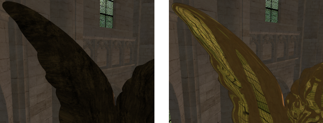
Part 4: Environment Mapped Reflections
Non-planar reflections are any kind of reflection that does not reflect around a single surface normal. These types of reflections can reflect any incoming light arriving from all around the object. Rendering these types of reflections requires knowing about the incoming light from all directions around the entire object. This can be achieved using an environment map which is located directly at the object location. This environment map can be created as a cube map so it stores lighting information for all incoming directions around the object. Reflections can then be calculated similar to a planar object except now the reflected light is calculated from the environment map.
- To support rendering environment mapped reflections, we need to first be able to detect these types of objects during scene load and store any required information. To create an environment map, we need to know the location to create the map at. This requires adding an additional variable to the
ReflectObjectDatatype.
struct ReflectObjectData
{
    ...
    // Cube map reflection data
    vec4 m_v4Position;
};
- Now we must update the code within
GL_LoadSceneNodeso that a second type of reflective object is made. We already have a variable inside the object type that stores if the object is not reflective ‘0’, planar reflective ‘1’ and now we will add environment reflective as ‘2’. We already have a check to see if the object is planar so any reflective object that is not will be handled by environment mapped reflections.
// Check if planar or not
if ( ... )
{
   ...
} else {
    // Set object as cube reflective
    p_Object->m_uiReflective = 2;
    ReflectObjectData * p_RObject = &SceneInfo.mp_ReflecObjects[SceneInfo.m_uiNumReflecObjects];

    // Set object position in reflective object
    p_RObject->m_uiObjectPos = SceneInfo.m_uiNumObjects;

    // *** Add environment map initialisation here ***

   ++SceneInfo.m_uiNumReflecObjects;
}
- To initialise the environment map texture, we need to create a new cube map texture. We will use the same texture variable that planar reflections use to store their texture (as a single object can only be 1 of them). This requires binding the texture as a cube map and then creating texture storage for all desired mipmap levels. As cube map faces have to be square, we will use the current window height as the cubes face size in both directions. Once the cube map has been allocated, we will initialise some texture filtering values and then finally calculate the environment maps model space position by calculating the centre of the meshes AABB.
// Generate texture for reflection map
glGenTextures(1, &p_Object->m_uiReflect);
glBindTexture(GL_TEXTURE_CUBE_MAP, p_Object->m_uiReflect);
int iLevels = (int)ceilf(log2f((float)g_iWindowHeight));
glTexStorage2D(GL_TEXTURE_CUBE_MAP, iLevels, GL_RGB8, g_iWindowHeight, g_iWindowHeight);

// Initialise the texture filtering and wrap values
glTexParameteri(GL_TEXTURE_CUBE_MAP, GL_TEXTURE_MIN_FILTER, GL_LINEAR_MIPMAP_LINEAR);
glTexParameteri(GL_TEXTURE_CUBE_MAP, GL_TEXTURE_MAG_FILTER, GL_LINEAR);
glTexParameterf(GL_TEXTURE_CUBE_MAP, GL_TEXTURE_MAX_ANISOTROPY_EXT, 4);
glTexParameteri(GL_TEXTURE_CUBE_MAP, GL_TEXTURE_WRAP_S, GL_CLAMP_TO_EDGE);
glTexParameteri(GL_TEXTURE_CUBE_MAP, GL_TEXTURE_WRAP_T, GL_CLAMP_TO_EDGE);

// Calculate AABB centre position in model space
p_RObject->m_v4Position = vec4(v3AABBMin + (v3AABBSize * 0.5f), 1.0f);
- Now we have initialised the cube map for environment reflections we need to update the fragment shader so that it can be used. To do this we will add an additional subroutine for
ReflectMap. This subroutine will be responsible for calculating the environment mapped reflections. This functions almost exactly like the planar reflection subroutine except that it uses the reflection direction vector to sample from a cube map instead.
layout(index = 6) subroutine(ReflectMap) vec3 textureReflectCube(vec3 v3ColourOut, vec3 v3Normal, vec3 v3ViewDirection, vec3 v3SpecularColour, float fRoughness)
{
    // Get reflect direction
    vec3 v3ReflectDirection = normalize(reflect(-v3ViewDirection, v3Normal));

    // Calculate LOD offset
    float fLOD = textureQueryLod(scReflectMapTexture, v3ReflectDirection).y;
    float fGloss = 1.0f - fRoughness;
    fLOD += ((2.0f / (fGloss * fGloss)) - 1.0f);

    // Get reflect texture data
    vec3 v3ReflectRadiance = textureLod(scReflectMapTexture, v3ReflectDirection, fLOD).xyz;

    // Perform shading
    vec3 v3RetColour = GGXReflect(v3Normal, v3ReflectDirection, v3ViewDirection, v3ReflectRadiance, v3SpecularColour, fRoughness);

    return v3ColourOut + v3RetColour;
}
- To use the environment map, we need to add another input texture. This texture will be bound to the next available location (in this case ‘5’).
layout(binding = 5) uniform samplerCube scReflectMapTexture;
- We now need to modify the object render loop to add the new subroutine binding (in this case ‘6’) to the list of available reflection subroutines
uiReflectSubs.
- Now within the object loop of the object render function we need to make sure the reflection cube map texture is bound whenever an environment mapped reflective object is detected. Since this texture was explicitly set to binding location ‘5’ we must set the texture to the corresponding texture binding.
// If reflective then update texture and uniform
if (p_Object->m_uiReflective == 1) {
    ...
} else if (p_Object->m_uiReflective == 2) {
    glActiveTexture(GL_TEXTURE5);
    glBindTexture(GL_TEXTURE_CUBE_MAP, p_Object->m_uiReflect);
}
Rendering to a cube map texture requires rendering the entire scene to each of the 6 cube faces. This can either be done using 6 separate render calls for each face or by using the geometry shader. When using the geometry shader, we can output 6 different vertices from the geometry shader for each single input vertex. Each of these output vertices is transformed based on the corresponding cube faces view projection. The geometry shader can then specify the layer each output vertex should occur at. This can be used to control which face the output fragment is rendered into. Using this technique allows for an entire cube map to be rendered in a single draw operation.
- For environment mapped reflections we need to create a new frame buffer that we can use to generate the required reflection texture. However, in this case we need to create a cube mapped texture. To do this we need to create a new framebuffer that will store output in a cube map. We will also create a new UBO that can be used to pass each of the 6 view projections for each face of the cube map to the geometry shader.
GLuint g_uiFBOCube;
GLuint g_uiDepthCube;
GLuint g_uiReflectVPUBO;
- Now within the initialisation function we need to create the new cube mapped frame buffer. This is done similar to the previous frame buffer except that the z-buffer storage must be a cube mapped texture. This texture has 6 faces and should be initialised in a similar way to how we initialised cube maps previously. We also need to initialise the UBO buffer that we use for passing data to the geometry shader.
// Create cube map frame buffer
glGenFramebuffers(1, &g_uiFBOCube);
glBindFramebuffer(GL_DRAW_FRAMEBUFFER, g_uiFBOCube);

// Create depth cube map
glGenTextures(1, &g_uiDepthCube);
glBindTexture(GL_TEXTURE_CUBE_MAP, g_uiDepthCube);
glTexStorage2D(GL_TEXTURE_CUBE_MAP, 1, GL_DEPTH_COMPONENT24, g_iWindowHeight, g_iWindowHeight);

// Attach buffers to FBO
glFramebufferTexture(GL_FRAMEBUFFER, GL_DEPTH_ATTACHMENT, g_uiDepthCube, 0);

// Generate a UBO for cube map view projection matrices
glGenBuffers(1, &g_uiReflectVPUBO);
- Make sure you add the necessary code to the programs quit function to delete the created frame buffer, texture and UBO.
- To actually generate the cube map, we need to write a new geometry shader. The geometry shader has a single UBO that passes in the view projection matrices for each of the 6 cube map faces. The geometry shader has an input array for each output of the vertex shader. So, in this case we have a position, normal and UV array. The reason they are passed as arrays is that the geometry shader takes as input all the vertices in each face. As we are rendering triangles there will only be 3 vertices in each face. The shader then has 3 outputs for position, normal and UV. Each vertex that is emitted from the geometry shader will output these variables (Note: multiple vertices can be output from a geometry shader). Since we are processing triangles the number of vertices output from the shader is specified using
layout(triangle_strip, max_vertices = 3) out. We use a special type of geometry shader invocation by usinglayout(triangles, invocations = 6) inwhich causes the geometry shader to be executed 6 times each in parallel. This is helpful for improving performance as now each of the 6 faces can be calculated in parallel. The actual contents of the geometry shader just loops over each vertex in the input triangle and transforms it based on the current output face of the cube map. Since we have used multiple invocations for each face then we can use thegl_InvocationIDvariable to get the index of the current invocation. This index can then be directly used as the index to the corresponding cube map face. We then transform the position and normal identically to how we previously did it in the vertex shader. We then use the inbuilt output variablegl_Layerto specify which layer of the attached output buffer to output any generated fragments to. This is because we have a cube map output attached so thegl_Layervariable is used to direct each output to the corresponding face in the texture. Once each vertex has been calculated we useEmitVertex()to pass that vertex on through the render pipeline. Finally, once all 3 vertices have been output we callEndPrimitive()to signal the end of vertex output.
#version 430 core

layout(binding = 4) uniform CameraCubeData {
    mat4 m4ViewProjectionCube[6];
};

layout(triangles, invocations = 6) in;
layout(triangle_strip, max_vertices = 3) out;

layout(location = 0) in vec3 v3VertexPos[];
layout(location = 1) in vec3 v3VertexNormal[];
layout(location = 2) in vec2 v2VertexUV[];

layout(location = 0) smooth out vec3 v3PositionOut;
layout(location = 1) smooth out vec3 v3NormalOut;
layout(location = 2) smooth out vec2 v2UVOut;

void main()
{
    // Loop over each vertex in the face and output
    for(int i = 0; i < 3; ++i) {
        // Transform position
        v3PositionOut = v3VertexPos[i];
        gl_Position = m4ViewProjectionCube[gl_InvocationID] * vec4(v3VertexPos[i], 1.0f);

        // Transform normal
        vec4 v4Normal = m4ViewProjectionCube[gl_InvocationID] * vec4(v3VertexNormal[i], 0.0f);
        v3NormalOut = v4Normal.xyz;

        //Pass-through UV coordinates
        v2UVOut = v2VertexUV[i];

        // Output to cubemap layer based on invocation ID
        gl_Layer = gl_InvocationID;
        EmitVertex();
    }
    EndPrimitive();
}
- Since the view projection transformation is now handled in the geometry shader, we need to create a new vertex shader that only calculates the world space variables. Do this by copying the existing vertex shader and then removing the code that transforms by the view projection matrix (remember to still keep the model to world space transform). Also remove the setting of
gl_Positionas this is done in the geometry shader and is not required in the vertex shader anymore.
- To load the geometry shader, we need to modify the existing function to load shaders so that it takes in an optional third parameter that can be used to pass a geometry shader. By default, this input will be set to ‘-1’ so existing code will still function without modification. We can then check the status of the geometry input and only attach a geometry shader if the input is not ‘-1’.
bool GL_LoadShaders(GLuint & uiShader, GLuint uiVertexShader, GLuint uiFragmentShader, GLuint uiGeometryShader)
{
    ...
    if (uiGeometryShader != -1) {
        glAttachShader(uiShader, uiGeometryShader);
    }
    ...
- Next modify your code so that there are now 2 OpenGL program variables. Add code to load in the new vertex shader and the new geometry shader. The geometry shader is loaded as a
GL_GEOMETRY_SHADERtype. Link the new vertex shader, geometry shader and the existing fragment shader together into the second program. Once done make sure that the light uniforms are correctly set for both programs (for instance the number of point lights should useglProgramUniform1ito set it for both programs). Also make sure you add code to delete each shader and program where necessary.
GLuint g_uiReflectProgram;
- Finally, we should update the render function so that it generates the environment map for each required object. This requires adding code to the existing loop that loops over each reflective object, determines the world space position for the object and then calculate the cube map view-projections for each face.
// Check if planar or cube reflection
if (p_Object->m_uiReflective == 1) {
    ...
} else if (p_Object->m_uiReflective == 2) {
    // Calculate position in world space
    vec3 v3Position = vec3(p_Object->m_4Transform * p_RObject->m_v4Position);

    // Calculate cube map VPs
    mat4 m4CubeViewProjections[6];
    GL_CalculateCubeMapVP(v3Position, m4CubeViewProjections, g_SceneData.m_LocalCamera.m_fNear, g_SceneData.m_LocalCamera.m_fFar);

    // *** Add environment reflection generation code here ***
- This requires making a new function
GL_CalculateCubeMapVPused to generate the view-projection matrices for each face of a cube map based on input near and far projection distances.
void GL_CalculateCubeMapVP(const vec3 & v3Position, mat4 * p_m4CubeViewProjections, float fNear, float fFar)
{

    // *** Add remaining code here ***
}
- Next within the new function we need to determine the view and up directions for each face of the cube map. Since each face is in world space, we can simply use a hardcoded table of values for these ensuring that we specify them in the correct order so it corresponds to the order that cube map faces are stored.
// World space normals
const vec3 v3CubeNormals[] = {
    vec3( 1.0f,  0.0f,  0.0f),     // positive x
    vec3(-1.0f,  0.0f,  0.0f),     // negative x
    vec3( 0.0f,  1.0f,  0.0f),     // positive y
    vec3( 0.0f, -1.0f,  0.0f),     // negative y
    vec3( 0.0f,  0.0f,  1.0f),     // positive z
    vec3( 0.0f,  0.0f, -1.0f),     // negative z
};

// World space up directions
const vec3 v3CubeUps[] = {
    vec3(0.0f, -1.0f,  0.0f),     // positive x
    vec3(0.0f, -1.0f,  0.0f),     // negative x
    vec3(0.0f,  0.0f,  1.0f),     // positive y
    vec3(0.0f,  0.0f, -1.0f),     // negative y
    vec3(0.0f, -1.0f,  0.0f),     // positive z
    vec3(0.0f, -1.0f,  0.0f),     // negative z
};
- Next, we can calculate the view and projection matrices for each face using the same functions we have used to create these matrices in the past. The only difference is that each cube map face has a projection field of view of exactly 90 degrees. Since each face is also square, they have a fixed aspect ratio of 1:1. We can then combine them in the return parameter as the final part of the function.
// Calculate view matrices
mat4 m4CubeViews[6];
for (unsigned i = 0; i < 6; i++) {
    m4CubeViews[i] = lookAt(v3Position,
                            v3Position + v3CubeNormals[i],
                            v3CubeUps[i]);
}

// Calculate projection matrix
mat4 m4CubeProjection = perspective(
    radians(90.0f),
    1.0f,
    fNear, fFar
    );

// Calculate combined view projection matrices
for (unsigned i = 0; i < 6; i++) {
    p_m4CubeViewProjections[i] = m4CubeProjection * m4CubeViews[i];
}
- Back in the reflection code we can use the result returned from
GL_CalculateCubeMapVPto pass that data into the UBO for the geometry shader.
// Update the objects projection UBO
glBindBuffer(GL_UNIFORM_BUFFER, g_uiReflectVPUBO);
glBufferData(GL_UNIFORM_BUFFER, sizeof(mat4) * 6, &m4CubeViewProjections[0], GL_STATIC_DRAW);
- So, the Fragment shader has the correct position value for lighting calculations we also need to pass the appropriate camera data. For this we will use the existing UBO that we used for planar reflections. Because the view-projection transform is performed in the geometry shader the only thing that the camera data needs is the correct position so we could put anything in as the view-projection (here well just use the first transform).
// Create updated camera data
CameraData Camera = {
    m4CubeViewProjections[0], //Does not matter
    v3Position};

// Update the camera buffer
glBindBuffer(GL_UNIFORM_BUFFER, g_uiReflectCameraUBO);
glBufferData(GL_UNIFORM_BUFFER, sizeof(CameraData), &Camera, GL_STATIC_DRAW);
glBindBufferBase(GL_UNIFORM_BUFFER, 1, g_uiReflectCameraUBO);
- Next, we can bind the frame buffer for cube map rendering and then set the objects reflection texture as the frame buffers attached colour buffer. We then change the program to use the second one and then bind the UBO used to pass data to the geometry shader.
// Bind cube map frame buffer
glBindFramebuffer(GL_DRAW_FRAMEBUFFER, g_uiFBOCube);

// Set render output to object texture
glFramebufferTexture(GL_DRAW_FRAMEBUFFER, GL_COLOR_ATTACHMENT0, p_Object->m_uiReflect, 0);

// Set the cube map program
glUseProgram(g_uiReflectProgram);

// Bind the UBO buffer
glBindBufferBase(GL_UNIFORM_BUFFER, 4, g_uiReflectVPUBO);
- Now we can render the objects into the attached cube frame buffer. However, since each face of the cube map now has a different resolution to the actual output window, we need to update the viewport used by OpenGL. The viewport tells OpenGL what part of a buffer can be written into. By default, this is set to the resolution of the current window. Because our cube map faces have a different resolution, we need to update the viewport using a call to
glViewport. Once completed we can now render the objects as normal while ensuring that the current object is not rendered. Once completed we reset the program and the viewport to standard.
// Update the viewport
glViewport(0, 0, g_iWindowHeight, g_iWindowHeight);

// Render other objects
GL_RenderObjects(p_Object);

// Reset to default program and viewport
glUseProgram(g_uiMainProgram);
glViewport(0, 0, g_iWindowWidth, g_iWindowHeight);
- Finally add code to bind the reflection texture and generate the required mipmaps using the same method we have used previously.
- You should now be able to run your program and see the effects of having environment mapped reflections. These will be seen on the brass statue.
Part 5: Extra
- Currently the reflection environment maps are calculated every frame. Currently this is not required as the contents of the reflection doesn’t change as nothing in the scene moves. You should modify the code so that the environment maps for each reflective object are calculated during initialisation instead as this will notably improve performance. This will require later detecting when an object moves and then updating the reflection maps as needed. To make this simpler you should place the code within its own function which can be called either during initialisation or rendering as needed.
- When calculating the environment map reflection care should be taken to ensure that the planar reflection is also correct with respect to the view of the environment reflection. Before calculating the environment map reflections, you should ensure that a planar reflection is generated based on the position of the environment map’s view (only those sides of the cube map that can see the reflection – hint this is positive z). To keep this simple, you should place the planar code within its own function that can be called with input view parameters. This way the same function can be called to calculate the reflection as seen by the environment map but also called to later to calculate the normal camera view reflection during rendering.
- The
ReflectObjectDatatype currently has 2 separatevec4’s where only 1 of them is ever used at a time depending on what type of reflection the object represents. The type can be optimised by only storing a single variable that can be used by both types of reflections. Update your code to apply this simplification.
- The glossiness of a surface’s material effects the clarity of the reflection. Try scaling the roughness value inside the fragment shader so you can see the different effects obtained with different roughness values.
Note: Optimisation
There are many ways to optimise code however some of the most effective revolve around optimising the output of geometry shaders. Geometry shaders have considerable cost due to the variable number of outputs that can be emitted from a single Geometry shader invocation. This adds costs within the renderer as it needs to dynamically manage output memory space. We can improve Geometry shader performance by reducing the number of output vertices. One way to do this is to manually perform frustum culling within the shader code. The Geometry shader we have been using for reflection mapping can be updated so that it also performs frustum culling and only outputs vertices if the triangle is within the view.
void main()
{
    vec4 v4PositionVPTemp[3];
    int iOutOfBound[6] = int[6](0, 0, 0, 0, 0, 0);
    // Loop over each vertex and get clip space position
    for (int i = 0; i < 3; ++i) {
        // Transform position
        v4PositionVPTemp[i] = m4ViewProjectionCube[gl_InvocationID] * vec4(v3VertexPos[i], 1.0f);

        // Check if any value is outside clip planes
        if (v4PositionVPTemp[i].x >  v4PositionVPTemp[i].w)
            iOutOfBound[0] = iOutOfBound[0] + 1;
        if (v4PositionVPTemp[i].x < -v4PositionVPTemp[i].w)
            iOutOfBound[1] = iOutOfBound[1] + 1;
        if (v4PositionVPTemp[i].y >  v4PositionVPTemp[i].w)
            iOutOfBound[2] = iOutOfBound[2] + 1;
        if (v4PositionVPTemp[i].y < -v4PositionVPTemp[i].w)
            iOutOfBound[3] = iOutOfBound[3] + 1;
        if (v4PositionVPTemp[i].z >  v4PositionVPTemp[i].w)
            iOutOfBound[4] = iOutOfBound[4] + 1;
        if (v4PositionVPTemp[i].z < -v4PositionVPTemp[i].w)
            iOutOfBound[5] = iOutOfBound[5] + 1;
    }

    // Loop over each clip face and check if triangle is completely outside
    bool bInFrustum = true;
    for (int i = 0; i < 6; ++i)
        if (iOutOfBound[i] == 3)
            bInFrustum = false;

    // If visible output triangle data
    if (bInFrustum) {
        // *** Existing geometry shader code goes here ***
    }
}