Tutorial 7: Shadows
- Part 1: Spot Lights
- Part 2: Shadow Mapping
- Part 3: Omni-Directional Shadow Mapping
- Part 4: Percentage Closer Filtering
- Part 5: Extra
- Note: Optimisation
This tutorial covers how to add shadows for point and spot lights.
This tutorial will continue on from the last by extending the previously created code. It is assumed that you have created a copy of last tutorial’s code that can be used for the remainder of this one.
Part 1: Spot Lights
- Previously we have been treating loaded spot lights the same as a point light. Now it is time to treat them separately. To do this we must create a new type to hold spot light data. Spot lights are similar to point lights except that they contain an additional direction vector that represents the direction the spot light is facing and an angle which represents the shape of the spots illumination cone along the spots direction vector.
struct SpotLightData
{
    aligned_vec3 m_v3Position;
    aligned_vec3 m_v3Direction;
    float m_fAngle;
    aligned_vec3 m_v3Colour;
    aligned_vec3 m_v3Falloff;
};
- Since spot lights need to be treated differently to point lights we must now store them separately. We need to add a new array to store the spot lights and a corresponding number of spot lights variable. We also need a separate UBO to pass the spot light array to the shader program. These all need to be added to the
SceneDataobject type.
struct SceneData
{
    ...
    SpotLightData * mp_SpotLights;
    unsigned m_uiNumSpotLights;
    GLuint m_uiSpotLightUBO;
    ...
};
- In the scene load function, you now need to ensure that the spot light array is allocated in the same location as the existing light array is allocated. Like the point light array, we will speculatively allocate enough memory to store all lights found in the scene such that it holds
p_Scene->mNumLightsnumber of lights.
- Now we need to load each spot light into the array. Modify the existing code so that only point lights are added to the existing light array and then add new code that detects and adds spot lights to the corresponding spot light array. Spot lights require the additional direction and angle values. The direction we will grab directly from Assimp except that we will negate it so that it points toward the light instead of away from the light. This simplifies calculations in the shader as existing light vectors are all treated as the direction to the light. We also grab the outer cone angle directly from Assimp. Since the outer cone angle represents the diameter of the cones angle we will half it so that it corresponds to the radius. We will then get the cosine of this angle so that we can directly use it to compare against the output of a dot product (since the dot product of 2 vectors equals the cosine of the angle between them).
} else if (p_AILight->mType == aiLightSource_SPOT) {
    // Get spot light
    SpotLightData * p_Light = &SceneInfo.mp_SpotLights[SceneInfo.m_uiNumSpotLights];
    vec3 v3Position = vec3(p_AILight->mPosition.x,
                           p_AILight->mPosition.y,
                           p_AILight->mPosition.z);
    p_Light->m_v3Position = (vec3)(m4Ret * vec4(v3Position, 1.0f));
    vec3 v3Direction = vec3(p_AILight->mDirection.x,
                            p_AILight->mDirection.y,
                            p_AILight->mDirection.z);
    p_Light->m_v3Direction = -normalize(mat3(m4Ret) * v3Direction);
    p_Light->m_fAngle = cos(p_AILight->mAngleOuterCone / 2.0f);
    p_Light->m_v3Colour = vec3(p_AILight->mColorDiffuse.r,
                               p_AILight->mColorDiffuse.g,
                               p_AILight->mColorDiffuse.b);
    // Divide linear and quadratic components by 2 to compensate for using a minimum constant of 1
    p_Light->m_v3Falloff = vec3(
        (p_AILight->mAttenuationConstant == 0.0f) ? 1.0f : p_AILight->mAttenuationConstant,
        p_AILight->mAttenuationLinear / 2.0f,
        p_AILight->mAttenuationQuadratic / 2.0f);
    ++SceneInfo.m_uiNumSpotLights;
}
- You should now add the corresponding code to initialise the spot light UBO with the contents of the spot light array in exactly the same way as the existing point light UBO is created. Finally add code to the scene unload function that will correctly free the new light array and delete the spot light UBO.
- Now we need to add code to the Fragment shader that will use the new spot light array. To do that we will first add the declaration of the spot light type. This type has the exact same variables as the host equivalent.
struct SpotLight {
    vec3 v3LightPosition;
    vec3 v3LightDirection;
    float fCosAngle;
    vec3 v3LightIntensity;
    vec3 v3Falloff;
};
- In the same manner as the point light array we now need to add an UBO that contains an array of spot lights as well as a uniform that holds the actual number contained in that array. Each of these new inputs should have binding and locations values set to the next available value (in this case the UBO uses binding location 5 and the uniform uses location 2).
layout(std140, binding = 5) uniform SpotLightData {
    SpotLight SpotLights[MAX_LIGHTS];
};
layout(location = 2) uniform int iNumSpotLights;
- We can now add the shader code to loop through the spot light array and add each lights contribution to the final output. This is almost identical to the point light loop except that we must check whether the current point is within the spots cone. To do this we get the dot product of the vector from the current position to the light and the lights inverse view direction. This gives the cosine angle between them. If this cosine is greater than (corresponding to an angle less than) the spots angle cut-off, then the light is within the cone and should be lit accordingly.
// Loop over each spot light
for (int i = 0; i < iNumSpotLights; i++) {
    vec3 v3LightDirection = normalize(SpotLights[i].v3LightPosition - v3PositionIn);

    // Check light angle
    float fLightAngle = dot(v3LightDirection, SpotLights[i].v3LightDirection);
    if (fLightAngle >= SpotLights[i].fCosAngle) {
        // Calculate light falloff
        vec3 v3LightIrradiance = lightFalloff(SpotLights[i].v3LightIntensity, SpotLights[i].v3Falloff, SpotLights[i].v3LightPosition, v3PositionIn);

        // Perform shading
        v3RetColour += GGX(v3Normal, v3LightDirection, v3ViewDirection, v3LightIrradiance, v3DiffuseColour, v3SpecularColour, fRoughness);
    }
}
- In order to use the updated shader code, you must now add code to the initialisation function after the scene has been loaded that will bind the spot light UBO and uniform with the shader program. Use
glBindBufferBasefor the UBO andglProgramUniform1ifor the number of spot lights (remember to bind for all programs).
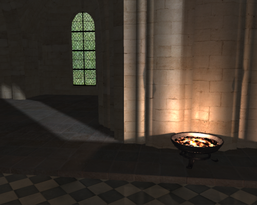
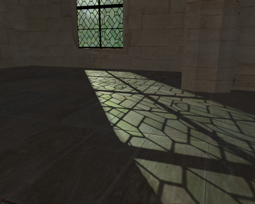
- You should now be able to compile and run your code in order to see the difference that using spot lights makes. You should now be able to see a spot light equivalent to the light coming in through each window in the tutorials example scene.
Part 2: Shadow Mapping
Rendering shadows requires a knowledge of where other objects are with respect to the currently rendered point in order to determine if they occlude the point’s view of the light. This problem can be solved by using Shadow Mapping. Shadow mapping involves rendering the scene from the point of view of the light and storing the distance to each visible surface as seen from that light. During normal rendering each visible point is then projected into the lights view and tested against the stored depth. If the point is closer or equal to the stored depth, then that point is being illuminated by the light. If the point is further away than the stored depth, then the point is in shadow.
- To use shadow mapping, we must first render the scene from the point of view of each light and store the rendered depth information. Determining the view from a light is easiest with spot lights as they already have a direction and an angle (which we can use as field of view) so for the moment we will focus on those. Since we have multiple spot lights we will use a technique similar to last tutorial where we use a geometry shader to render all the shadow maps in a single pass. To do this we need to create a new frame buffer, an output texture array that will be used to store all the depth maps for each spot light and a UBO that will store the view-projection information for each spot light.
GLuint g_uiFBOShadow;
GLuint g_uiShadowArray;
GLuint g_uiShadowUBO;
- We now need to initialise the framebuffer. This is done similar to previous tutorials except that after the framebuffer is created we will disable the use of a draw buffer. The draw buffers are used to store additional output information (e.g. colour) beyond the z-buffer. Since we only need the depth information we will disable all these outputs.
// Create shadow map frame buffer
glGenFramebuffers(1, &g_uiFBOShadow);
glBindFramebuffer(GL_FRAMEBUFFER, g_uiFBOShadow);

// Disable colour buffer output
glDrawBuffer(GL_NONE);
- Next we need to generate the array of depth textures that we will use to render the depth information into. As this is an array of 2D textures we must use
glTexStorage3Dto allocate the texture where we set the depth value to the number of images in the array. We set the type of texture toGL_DEPTH_COMPONENT32Fwhich will create a depth texture but using 32bit floating point instead of 24bit integer as has been used previously. This will help give the shadow map maximum quality to help in minimising errors.
// Generate array of spot light shadow map textures
glGenTextures(1, &g_uiShadowArray);
glBindTexture(GL_TEXTURE_2D_ARRAY, g_uiShadowArray);
glTexStorage3D(GL_TEXTURE_2D_ARRAY, 1, GL_DEPTH_COMPONENT32F, g_iWindowWidth, g_iWindowWidth, g_SceneData.m_uiNumSpotLights);
- Now we need to setup up the texture filtering setting for the new depth array. Depth maps cannot be filtered in the same way as a normal texture so we need to specify that filtering should occur using depth comparisons. We do this by setting
GL_TEXTURE_COMPARE_MODEto tell the sampler to perform filtering by comparing the values in the texture to a reference valueGL_COMPARE_REF_TO_TEXTURE. We then set the compare functionGL_TEXTURE_COMPARE_FUNCto use a less-or-equal operation. This way a lookup in the texture will return either a ‘1’ or a ‘0’ to signal if the current reference value (in this case our depth) is less than or equal to the value in the texture or not. When using Bilinear filtering the lookup will still return either a ‘1’ or ‘0’ but this time it will check all neighbouring texels and only return ‘1’ if the majority of texel checks are closer than the reference value. Since we don’t want anything outside the shadow map to receive light we set the filtering to clamp to the texture border and set the border value to zero (i.e. no depth which prevents reference values being closer than it).
glTexParameteri(GL_TEXTURE_2D_ARRAY, GL_TEXTURE_MAG_FILTER, GL_LINEAR);
glTexParameteri(GL_TEXTURE_2D_ARRAY, GL_TEXTURE_MIN_FILTER, GL_LINEAR);
glTexParameteri(GL_TEXTURE_2D_ARRAY, GL_TEXTURE_COMPARE_MODE, GL_COMPARE_REF_TO_TEXTURE);
glTexParameteri(GL_TEXTURE_2D_ARRAY, GL_TEXTURE_COMPARE_FUNC, GL_LEQUAL);
glTexParameteri(GL_TEXTURE_2D_ARRAY, GL_TEXTURE_WRAP_S, GL_CLAMP_TO_BORDER);
glTexParameteri(GL_TEXTURE_2D_ARRAY, GL_TEXTURE_WRAP_T, GL_CLAMP_TO_BORDER);
const GLfloat fMinDepth[] = {0.0f, 0.0f, 0.0f, 0.0f};
glTexParameterfv(GL_TEXTURE_2D_ARRAY, GL_TEXTURE_BORDER_COLOR, (GLfloat *)&fMinDepth);
- Now you should add code to generate the new shadow map UBO. Also add code that releases the framebuffer, shadow texture and UBO in the programs quit function.
- To render the shadow maps, we need to create a new shader program. This program doesn’t need to do any texturing or lighting as it only writes to the depth buffer. The vertex shader for the new program will therefore only take in an input vertex position and transform it into world space.
#version 430 core

layout(binding = 0) uniform TransformData {
    mat4 m4Transform;
};

layout(location = 0) in vec3 v3VertexPos;
layout(location = 0) smooth out vec3 v3PositionOut;

void main()
{
    // Transform vertex
    vec4 v4Position = m4Transform * vec4(v3VertexPos, 1.0f);
    v3PositionOut = v4Position.xyz;
}
- We need to create a geometry shader that will then transform each input world position input triangle into each lights view-projection space. This shader takes as input the UBO containing the array of light view-projections. It then uses these to transform each triangle and output it to the corresponding image in the output array by using
gl_Layerto control which image the output triangle will be rendered into. We will use invocations to allow the geometry shader to be run in parallel. We set the number of invocations to the maximum number of lights. In this case we set the number of lights to 32 which is the maximum number of invocations supported by many GPUs. Since the invocation number is fixed we therefore need to have an additional input uniform that sets the number of actual lights being rendered. Any geometry shader invocation after the number of actual lights will just do nothing. Doing nothing still has some amount of performance cost so in general it is best to ensure that the number of invocations is as close as possible to the number of lights actually being rendered.
#version 430 core

#define MAX_LIGHTS 32
layout(binding = 6) uniform CameraShadowData {
    mat4 m4ViewProjectionShadow[MAX_LIGHTS];
};

layout(location = 0) uniform int iNumLights;

layout(triangles, invocations = MAX_LIGHTS) in;
layout(triangle_strip, max_vertices = 3) out;

layout(location = 0) in vec3 v3VertexPos[];

void main()
{
    // Check if valid invocation
    if (gl_InvocationID < iNumLights) {
        // Loop over each vertex in the face and output
        for (int i = 0; i < 3; ++i) {
            // Transform position
            gl_Position = m4ViewProjectionShadow[gl_InvocationID] * vec4(v3VertexPos[i], 1.0f);

            // Output to array layer based on invocation ID
            gl_Layer = gl_InvocationID;
            EmitVertex();
        }
        EndPrimitive();
    }
}
- The fragment shader will just pass the depth value directly to the attached depth buffer so all that needs to be done is pass through the fragment depth.
#version 430 core
layout(location = 0) out float fFragDepth;

void main()
{
    // Not really needed, OpenGL does it anyway
    fFragDepth = gl_FragCoord.z;
}
- Add code to the initialisation function to load and link the new shader program using the new vertex, geometry and fragment shader.
GLuint g_uiShadowProgram;
- Now we can add code to create the shadow maps. This code should be added before the creation of any reflection textures so that the reflections contain the correct shadows. To create the shadow maps, we need to bind the framebuffer, set the correct shader program and then set the viewport to have the same resolution as the shadow map textures. Here we will just use the windows width to create a square texture.
// Bind shadow map frame buffer
glBindFramebuffer(GL_DRAW_FRAMEBUFFER, g_uiFBOShadow);

// Update the program and viewport
glUseProgram(g_uiShadowProgram);
glViewport(0, 0, g_iWindowWidth, g_iWindowWidth);
- Next we need to generate the view-projections for each of the spot lights and add them to the corresponding UBO.
unsigned uiSizeLights = sizeof(mat4) * g_SceneData.m_uiNumSpotLights;
mat4 * p_ViewProjections = (mat4 *)malloc(uiSizeLights);

// *** Add spot light view projection matrix generation here ***

// Fill shadow UBO
glBindBuffer(GL_UNIFORM_BUFFER, g_uiShadowUBO);
glBufferData(GL_UNIFORM_BUFFER, uiSizeLights, p_ViewProjections, GL_STATIC_DRAW);

free(p_ViewProjections);
- Generating the view-projection matrices for each spot just requires looping over each light and using its position and direction to create a view matrix (the up direction doesn’t matter so we just use the global up direction). We can then create the spot lights projection matrix by using the lights cone angle. Since we transformed the cone angle to a cosine during scene loading in order to improve shader performance we need to convert it back by using an inverse cosine. To maximise the resolution of the shadow map over the lights effective range we set the far distance of the projection based on the lights falloff value. This falloff value should then be clipped against the scene bounds, however for simplicity we will just clip it based on the cameras current far depth.
// Generate spot light view projection matrices
for (unsigned i = 0; i < g_SceneData.m_uiNumSpotLights; i++) {
    SpotLightData * p_SpotLight = &g_SceneData.mp_SpotLights[i];

    // Calculate view matrix
    mat4 m4LightView = lookAt(p_SpotLight->m_v3Position,
                              p_SpotLight->m_v3Position - p_SpotLight->m_v3Direction,
                              vec3(0.0f, 1.0f, 0.0f));

    // Get falloff distance
    float fFalloff = GL_CalculateFalloffDistance(p_SpotLight->m_v3Falloff);

    // Clamp falloff to scene bounds
    fFalloff = min(fFalloff, g_SceneData.m_LocalCamera.m_fFar * 1.5f);

    // Calculate projection matrix
    mat4 m4LightProjection = perspective(
        acos(p_SpotLight->m_fAngle) * 2.0f,
        1.0f,
        0.1f, fFalloff
        );

    p_ViewProjections[i] = m4LightProjection * m4LightView;
}
- Calculating the falloff distance of a light requires determining the distance from the light that the lights contribution nears zero (or some threshold value close enough to it). For a light using only constant falloff this point will never be reached (as the light contribution is the same irrespective of distance). However, for lights with either linear or quadratic falloff this distance can be calculated. Since most lighting is done using standard textures that only have 8bits per channel then the maximum number of discrete colour values per channel is 256. We can use this to define a threshold as anything less than a 256th of the original value is less than what a standard materials input textures can define anyway. We then check if the falloff function has a quadratic component and if it does we use the quadratic equation to determine at what distance the falloff becomes 1/256th of its full value. If the falloff is not quadratic but has a linear component, we can then use a simpler equation to perform the same operation when using linear falloff.
float GL_CalculateFalloffDistance(const vec3 & v3Falloff)
{
    // Calculate falloff size
    const float fFalloffThreshold = 256.0f;
    float fK0 = v3Falloff.x;
    float fK1 = v3Falloff.y;
    float fK2 = v3Falloff.z;
    float fFalloff = FLT_MAX;
    if (fK2 != 0.0f) {
        // Use Quadratic falloff
        fFalloff = -fK1 + sqrt((fK1 * fK1) - (4.0f * fK2 * (fK0 - fFalloffThreshold)));
        fFalloff /= 2.0f * fK2;
    } else if (fK1 != 0.0f) {
        // Use linear falloff
        fFalloff = (fFalloffThreshold - fK0) / fK1;
    }
    return fFalloff;
}
- Now that the lights view-projections have been generated and added to the UBO we need to bind the UBO to the new shader program (here we have specified the input UBO uses binding location ‘6’). We then set the geometry shaders input number of lights uniform, bind the shadow map framebuffer and then render each object. Since we don’t need to know about textures or any material or lighting information to generate the shadow maps we can therefore use a much simpler rendering loop to render to a shadow map.
// Bind shadow map UBO
glBindBufferBase(GL_UNIFORM_BUFFER, 6, g_uiShadowUBO);

// Update number of valid lights
glProgramUniform1i(g_uiShadowProgram, 0, g_SceneData.m_uiNumSpotLights);

// Attach buffers to FBO
glFramebufferTexture(GL_FRAMEBUFFER, GL_DEPTH_ATTACHMENT, g_uiShadowArray, 0);

GL_RenderObjectsDepth();
- To render objects to a depth map we just have to loop through each one and only bind its VAO and transform UBO. No other information is needed. We also change the way the back buffer is cleared as now we only have a depth component. We also make sure that any transparent object is skipped as otherwise the shadow map will think they are solid objects which will cause them to cast solid shadows. To allow light to travel through transparent objects we make sure they are not rendered to the shadow map.
void GL_RenderObjectsDepth()
{
    // Clear the depth buffer
    glClear(GL_DEPTH_BUFFER_BIT);

    // Loop through each object
    for (unsigned i = 0; i < g_SceneData.m_uiNumObjects; i++) {
        const ObjectData * p_Object = &g_SceneData.mp_Objects[i];

        // Skip if transparent
        if (p_Object->m_bTransparent)
            continue;

        // Bind VAO
        glBindVertexArray(p_Object->m_uiVAO);

        // Bind the Transform UBO
        glBindBufferBase(GL_UNIFORM_BUFFER, 0, p_Object->m_uiTransformUBO);

        // Draw the Object
        glDrawElements(GL_TRIANGLES, p_Object->m_uiNumIndices, GL_UNSIGNED_INT, 0);
    }
}
- Finally add code to reset the program and the viewport to the original values.
- Now we have added code to render the shadow maps we need to now add the code to our existing fragment shader so that it can use this new shadow information. To do this the shader needs access to the shadow map array texture that holds each of the shadow maps for each spot light. Since this is a depth texture we need to use a
sampler2DArrayShadowtype as we have set the texture to use depth comparisons when retrieving texel information. This texture is bound to the next available texture unit (in this case ‘6’). We also need the UBO containing each spot lights view-projection matrices so that we can project each rendered point into the lights view. This UBO is already bound to binding location ‘6’ so we will reuse the existing binding.
layout(binding = 6) uniform CameraShadowData {
    mat4 m4ViewProjectionShadow[MAX_LIGHTS];
};
layout(binding = 6) uniform sampler2DArrayShadow s2aShadowTexture;
- We will now add a shader function that will perform the shadow map lookup. This function will project the current position into a specific lights view. The light to use is passed in using an input parameter that specifies which element of the input UBO/texture array we are using. The light view position then needs to be converted from clip-space to texture coordinates the same way we did in the previous tutorial. We then lookup the value of the texture at this location. Since we are using a texture array we need to pass the UV coordinates as well as the index of the texture in the array that we want to look up. As this is a shadow texture object we also need to pass the current points depth with respect to the light. This depth is used internally as the reference value when performing texture lookups. OpenGL will then use this depth and return ‘1’ if that value is closer or equal to the value from the texel lookup.
float lightSpotShadow(in int iLight, in vec3 v3Position)
{
    // Get position in shadow texture
    vec4 v4SVPPosition = m4ViewProjectionShadow[iLight] * vec4(v3Position, 1.0f);
    vec3 v3SVPPosition = v4SVPPosition.xyz / v4SVPPosition.w;
    v3SVPPosition = (v3SVPPosition + 1.0f) * 0.5f;

    // Get texture value
    return texture(s2aShadowTexture, vec4(v3SVPPosition.xy, iLight, v3SVPPosition.z));
}
- We now need to modify the spot light loop in the main fragment shader function so that it calls the new shadow function and multiplies the shading contribution for that light. This way if the point is in shadow the contribution is multiplied by zero which causes it to appear black. If the point is being lit, then the contribution is multiplied by one which results in it being lit as normal.
// Calculate shadowing
float fShadowing = lightSpotShadow(i, v3PositionIn);
v3LightIrradiance *= fShadowing;
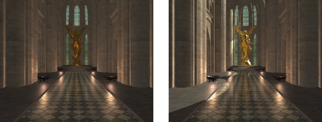
- We now have enough code to render with shadow maps. First ensure that the shadow map texture is bound to the appropriate texture unit (in this tutorial we have used ‘6’ which only needs to be bound once so it can be added to the initialise function – after binding the texture you should reset the active texture unit to unit 0 so that any future texture functions don’t mess up the current unit). After which you can now run your program and see the effects of using shadow maps for the spot lights. Spot lights are used in the example scene to create the light coming in through the windows.
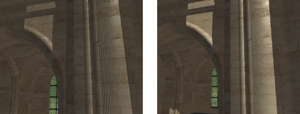
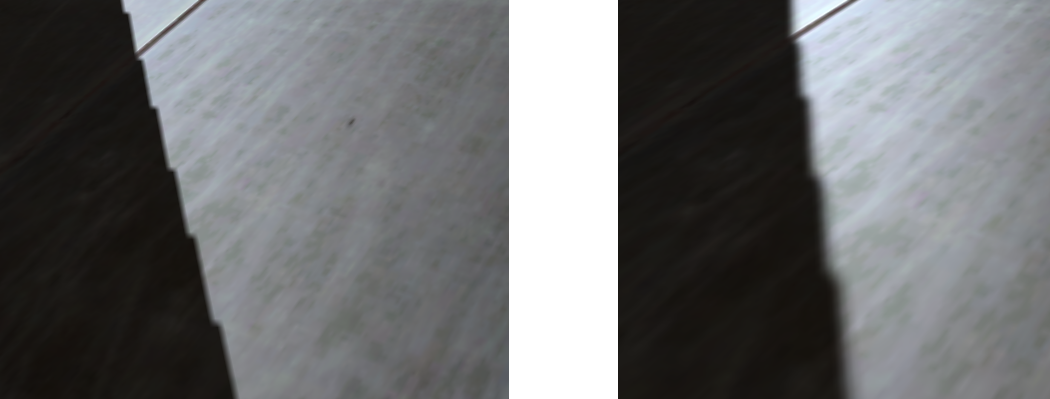
- You’ll notice after running the program that there is a lot of shadow acne over the lit surfaces. This is because of errors caused by the limited resolution of the shadow map. To try and overcome this we need to add a bias to shadow map lookups that compensates for any error. This can either be done in the shader program or when actually creating the shadow map. When using the latter, we can use an inbuilt OpenGL function
glPolygonOffsetto offset all the values stored into the shadow map by adding a bias to them. This function takes as input 2 bias values where the latter is an absolute offset value and the former is based on the slope of the rendered surface. Increasing the bias based on the slope of a surface is necessary to overcome projection errors as the higher a surfaces slope the larger the projected area of the corresponding texel in the shadow map. We then enable the bias values by enablingGL_POLYGON_OFFSET_FILLbefore rendering the shadow maps. To further improve shadow quality we will use front face culling to render only the back faces into the shadow map. This will improve the shadows on the front surface of objects as only the backside of occluding objects will be stored in the shadow map. Care should be taken to ensure that the bias values are then disabled and culling returned back to back face culling before regular rendering occurs.
// Setup culling and depth bias
glCullFace(GL_FRONT);
glPolygonOffset(0.9f, 0.0f);
glEnable(GL_POLYGON_OFFSET_FILL);

// *** Code to render shadow maps goes here ***

// Reset culling and depth bias
glCullFace(GL_BACK);
glDisable(GL_POLYGON_OFFSET_FILL);
Part 3: Omni-Directional Shadow Mapping
Standard shadow mapping cannot be used for point lights as this type of light radiates in all surrounding directions. As a result, it cannot be represented using a single shadow map. An often used solution is to instead use a cube map to store all surrounding shadow maps. This essentially results in 6 shadow maps being generated for a single point light so that each surrounding exitant direction is accounted for.
- To support point light shadows, we need to generate a cube shadow map for each point light. We can do this by creating an array of cube map textures and then reuse the existing shadow framebuffer. So in order to render to a shadow cube map array we first need to add the texture and a UBO to store the cube map view-projections.
GLuint g_uiShadowCubeArray;
GLuint g_uiShadowCubeUBO;
- Add code to the initialisation function to generate the new texture and UBO. This will be exactly the same as the code used to generate the spot light texture array except this time we must use a cube map array
GL_TEXTURE_CUBE_MAP_ARRAYinstead. You should also add the corresponding code to clean-up the new texture and UBO to the programs quit function.
- To access data from a cube map shadow texture we need to have a reference value to compare against the texture values. This requires determining the distance from the light in the lights view space. We can do this directly from the projections near and far distance values. To use these values, we need to add them to the existing definition of a point light (Note: beware of data alignment as the GPU will expect the
vec2to be aligned on a 128bit boundary. This will require adding appropriate padding between elements. To ensure this we use an aligned vector type).
struct PointLightData
{
    ...
    aligned_vec2 m_v2NearFar;
};
- To render the cube map shadow array, we can use exactly the same program that we used to render the spot light shadow array. This is because a cube map is essentially an array of 6 textures. So a cube map array is just an array with 6 times as many textures in it. Each of these textures can be accessed using the texture layer the same as we did for the spot light array. We can therefore add code to where the existing shadow maps are created to also create the point light shadow maps. This new code should go after the shadow map program, viewport and polygon offset have been setup but before any spot light shadow map code (Note: it can go after the spot light shadow code but since we will be using the same UBO binding to pass the point light view-projection matrices then whatever the last shadow map call was will be what is in the UBO binding. Since we use this UBO as the spot light input for normal rendering we have to ensure the spot light UBO is the one bound. If we render the point lights last you just have to ensure you rebind the spot light UBO).
unsigned uiSizeLights = sizeof(mat4) * g_SceneData.m_uiNumPointLights * 6;
mat4 * p_ViewProjections = (mat4 *)malloc(uiSizeLights);

// *** Add point light view projection matrix generation here ***

// Update point light UBO with new near/far values
glBindBuffer(GL_UNIFORM_BUFFER, g_SceneData.m_uiPointLightUBO);
glBufferData(GL_UNIFORM_BUFFER, sizeof(PointLightData) * g_SceneData.m_uiNumPointLights, g_SceneData.mp_PointLights, GL_STATIC_DRAW);

// Fill shadow UBO
glBindBuffer(GL_UNIFORM_BUFFER, g_uiShadowCubeUBO);
glBufferData(GL_UNIFORM_BUFFER, uiSizeLights, p_ViewProjections, GL_STATIC_DRAW);

free(p_ViewProjections);
- Generating the view-projection matrices just requires looping over each point light. We can use the existing function to calculate the falloff distance that we will use for the projection coefficients. Finally, we will use
GL_CalculateCubeMapVPwhich corresponds to the same code used in the last tutorial to generate the cube map view-projections around a specific point with specific near and far projection values. Since we update the near and far values here this is why we need to ensure the UBO is updated to contain the new values.
// Generate point light view projection matrices
for (unsigned i = 0; i < g_SceneData.m_uiNumPointLights; i++) {
    PointLightData * p_PointLight = &g_SceneData.mp_PointLights[i];

    // Get falloff distance
    float fFalloff = GL_CalculateFalloffDistance(p_PointLight->m_v3Falloff);

    // Clamp falloff to scene bounds
    fFalloff = min(fFalloff, g_SceneData.m_LocalCamera.m_fFar);

    // Update lights near and far plane
    p_PointLight->m_v2NearFar = vec2(0.1f, fFalloff);

    // Calculate cube map VPs
    GL_CalculateCubeMapVP(p_PointLight->m_v3Position, &p_ViewProjections[i * 6],
        p_PointLight->m_v2NearFar.x, p_PointLight->m_v2NearFar.y);
}
- Now the UBO has been filled we can bind it to our existing shadow map program. We then pass the number of shadow maps to render (since each point light has six faces this number is six times the number of lights) and then attach our cube map array to the frame buffer.
// Update number of valid lights
glProgramUniform1i(g_uiShadowProgram, 0, g_SceneData.m_uiNumPointLights * 6);

// Bind shadow map UBO
glBindBufferBase(GL_UNIFORM_BUFFER, 6, g_uiShadowCubeUBO);

// Attach buffers to FBO
glFramebufferTexture(GL_FRAMEBUFFER, GL_DEPTH_ATTACHMENT, g_uiShadowCubeArray, 0);
- With the newly created shadow maps we can now update the normal fragment shader code to use shadow information for point light rendering. This requires updating the point light definition to include the new near far variable. It also requires adding the cube map shadow array as an input texture to the next available texture binding location (in this case it is ‘7’).
struct PointLight {
    ...
    vec2 v2NearFar;
};
layout(binding = 7) uniform samplerCubeArrayShadow scaPointShadowTexture;
- Next we need to add a function to calculate the shadowing for each point light. This function will be similar to the spot light function but it has several additional input values. The first couple are the un-normalised direction vector from the current point and the light and then the normalised vector. We use the un-normalised vector to get the distance from the point to the light while we use the normalized vector to access the cube map. Lastly we need the current lights near far distance values so we can calculate where we are with respect to the lights projection values. We use these values to transform the calculated distance to the light into the lights projection space and then convert these to the required texture range. Because we are accessing a cube map we need to determine which cube map face we are accessing and then the depth within that face. The correct cube map face is determined by the component of the light direction vector that has the greatest magnitude. This magnitude is the corresponding depth into that face (e.g. if we are reading from the +x face then it is the +x direction that is now our depth). The resulting value can then be used to compare against the values stored in the shadow map. Since we are now accessing shadow texels from a cube map array we need to pass the texture function the current direction from the light to the point and the index of the required cube map in the array. We then pass the comparison reference depth as an additional parameter.
float lightPointShadow(in int iLight, in vec3 v3LightDirection, in vec3 v3LightDirectionUN, in vec2 v2NearFar, in vec3 v3Position)
{
    // Get depth in shadow texture
    vec3 v3AbsDirect = abs(v3LightDirectionUN);
    float fDist = max(v3AbsDirect.x, max(v3AbsDirect.y, v3AbsDirect.z));
    float fDepth = (v2NearFar.y + v2NearFar.x) * fDist;
    fDepth += (-2 * v2NearFar.y * v2NearFar.x);
    fDepth /= (v2NearFar.y - v2NearFar.x) * fDist;
    fDepth = (fDepth * 0.5) + 0.5;

    // Get texture value
    return texture(scaPointShadowTexture, vec4(-v3LightDirection, iLight), fDepth);
}
- Next add code to the main point light render loop to call the new point light shadow function. The result of this function call should then be used to modify the lights shading in exactly the same way that we did for the spot light.
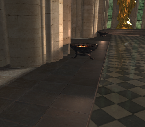
- Finally make sure that the point light shadow map is bound to the appropriate texture binding (in this case it is ‘7’ and as this doesn’t change it only needs to be set once during initialisation). You should now be able to run your program and see the effects of using point light shadow maps. Each of the tutorials example scenes braziers has a single point light attached to it. You should be able to observe the shadowing effects caused by these lights.
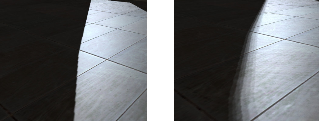
Part 4: Percentage Closer Filtering
Normal shadow mapping results in hard shadows along shadow boundaries. These shadow boundaries often show aliasing effects due to the resolution of the shadow map. Percentage closer filtering is a technique that attempts to soften the edges around shadow boundaries by sampling many nearby shadow map texels and averaging their contribution. Unlike regular texture filtering the values stored in the shadow map cannot be averaged. Instead the shadow map texels should be checked against the current depth value and then the result of that comparison should be averaged over each sampled texel. This has the effect of softening the transition at the shadow boundary by adding an additional shadow gradient. Where the number of steps in the gradient corresponds to the number of samples averaged.
- To help smooth the shadow edges we will employ PCF to sample multiple texels. To do this we will need to sample many shadow map texels. To keep computation cost low, we will sample 9 texels around the current position. This can be done using a grid with the current texel in the centre however this will result in obvious banding artefacts due to the square layout of texture samples. To help alleviate this we will use a set of precomputed Poisson disk values to sample around the current texel. To do this we need to know the size of each texel so we can determine the coordinates for a neighbouring texel. We can do this by using the GLSL function
textureSizeto return the resolution of the current texture and then use that to get the size of each texel. The existing spot light texture lookup should be replaced by the following code.
// Define Poisson disk sampling values
const vec2 v2PoissonDisk[9] = vec2[](
    vec2(-0.01529481f, -0.07395129f),
    vec2(-0.56232890f, -0.36484920f),
    vec2( 0.95519960f,  0.18418130f),
    vec2( 0.20716880f,  0.49262790f),
    vec2(-0.01290792f, -0.95755550f),
    vec2( 0.68047200f, -0.51716110f),
    vec2(-0.60139470f,  0.37665210f),
    vec2(-0.40243310f,  0.86631060f),
    vec2(-0.96646290f, -0.04688413f));

// Get Texture dimensions
int iTextSize = textureSize(s2aShadowTexture, 0).x;
float fShadowSize = 1.0f / iTextSize;

// Perform additional filtering
float fShadowing = 0.0f;
for (int i = 0 ; i <= 9 ; i++) {
    vec2 v2Offset = v2PoissonDisk[i] * fShadowSize;
    vec3 v3UVC = v3SVPPosition + vec3(v2Offset, 0.0f);
    float fText = texture(s2aShadowTexture, vec4(v3UVC.xy, iLight, v3UVC.z));
    fShadowing += fText;
}

return fShadowing / 9;
- Since point lights require three-dimensional lookup inputs we need to define a different set of Poisson disk values. By projecting the existing Poisson values onto a sphere we can derive a new set of values that will sample around an existing vector in three-dimensions. This code will then use these new Poisson values to perform PCF sampling similar to that used by the spot light code. This should replace the existing point light texture lookup.
// Define Poisson sampling values
const vec3 v3PoissonDisk[9] = vec3[](
    vec3(-0.023860920f, -0.115901396f,  0.985948205f),
    vec3(-0.649357200f, -0.542242587f,  0.066411376f),
    vec3( 0.956068397f,  0.285292149f, -0.865215898f),
    vec3( 0.228669465f,  0.698871136f,  0.355417848f),
    vec3(-0.001350721f, -0.997778296f, -0.866783142f),
    vec3( 0.602961421f, -0.725908756f, -0.338202178f),
    vec3(-0.672571659f,  0.557726085f, -0.027191758f),
    vec3(-0.123172671f,  0.978031158f, -0.663645744f),
    vec3(-0.995905936f, -0.073578961f, -0.894974828f));

// Get Texture dimensions
int iTextSize = textureSize(scaPointShadowTexture, 0).x;
float fShadowSize = 1.0f / iTextSize;

// Perform additional filtering
float fShadowing = 0.0f;
for (int i = 0 ; i <= 9 ; i++) {
    vec3 v3Offset = v3PoissonDisk[i] * fShadowSize;
    vec3 v3UVC = -v3LightDirection + v3Offset;
    float fText = texture(scaPointShadowTexture, vec4(v3UVC, iLight), fDepth);
    fShadowing += fText;
}

return fShadowing / 9.0f;
- You should now be able to run your program and notice the effects of using PCF. This will be most noticeable at the boundaries of shadow regions which will be the most obvious at the edges of the spot light shadows.
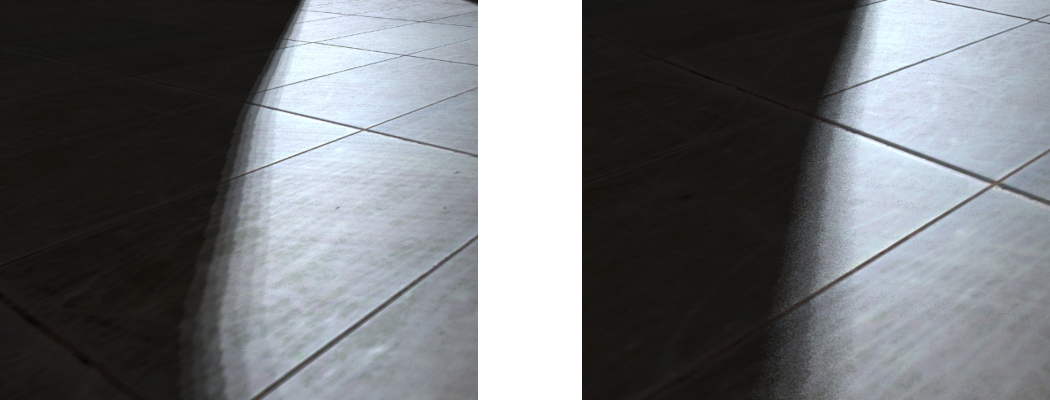
- PCF can also be used to generate soft shadows. By increasing the size that PCF samples over we can increase the size of the shadow transition. This can be used to give shadows a softer edge. In the real world a shadow should get softer the further a point is away from the light. We can approximate this effect by determining the visible size of the light as seen by the current point. And then increasing the size of the PCF filtered area accordingly. Since point and spot lights don’t have an actual size we first create a variable used to hold an equivalent size if the light actually existed. This size is created in the lights view-projection space by defining its area across the lights near plane. We can then approximate the size seen from the point by determining its distance from the light and increasing the visible size the further an object is away from the light (this roughly corresponds to the lights projected area increasing the further away from the light you go). This new value can be used to replace the definition of the
fShadowSizevariable used previously in the spot light shadow code.
// Light perspective space size of lights area on near plane
const float fLightSize = 0.07f;

// Approximate near plane size of light
float fShadowRegion = fLightSize * v3SVPPosition.z;
float fShadowSize = fShadowRegion / 9.0f;
- Equivalent code can be used for point lights by using
fDepthinstead ofv3SVPPosition.zin the shadow size calculation. You should add this code to the point light function as well.
- You should now be able to run the program and see the effects of soft shadows.
- The shadow boundaries have banding artefacts due to sampling errors in the PCF lookup. These banding artefacts can be replaced by noise which is often less objectionable to the human eye. We can do this by adding random variability to the way we sample texels in the PCF code. Instead of using the same Poisson values each texel lookup we can instead randomly rotate the Poisson disk to give a different set of sampling values. To do this we need to be able to randomly generate a value in shader code. To do this we will create a new function that will randomly generate a number based on an input position and an input frequency of randomness.
float random(in vec3 v3Seed, in float fFreq)
{
   // Project seed on random constant vector
   float fdt = dot(floor(v3Seed * fFreq), vec3(53.1215f, 21.1352f, 9.1322f));
   // Return only fractional part (range 0->1)
   return fract(sin(fdt) * 2105.2354f);
}
- We can then use this function to generate a new angle of rotation based on the current world space position. We use world space so that the generated random noise is fixed for each visible point. Using something like the view space position will result in the noise randomly changing as the view moves which is undesirable. We then create rotation coefficients by calculating the sine and cosine of the random angle.
// Generate random rotation
float fAngle = random(v3Position, 500.0f) * (M_PI * 2.0f);
vec2 v2Rotate = vec2(sin(fAngle), cos(fAngle));
- In the spot light code, we can then use this rotation value to transform the existing Poisson disk by the random rotation by performing a 2D rotation. The new rotated value can then be used for each texel lookup instead.
for (int i = 0 ; i <= 9 ; i++) {
    vec2 v2RotatedPoisson = (v2PoissonDisk[i].x * v2Rotate.yx) +
        (v2PoissonDisk[i].y * v2Rotate * vec2(-1.0f, 1.0f));
    vec2 v2Offset = v2RotatedPoisson * fShadowSize;
    ...
- To use a random rotation in the point light code we instead need to perform a 3D rotation. We can do this by creating two different rotations around the z and x axis using the same rotation coefficient. The combined rotation will then rotate in 3D space. This requires creating
v3Rotatewhich is the same asv2Rotateexcept that it has a third value set to 1.
vec3 v3RotatedPoisson = (v3PoissonDisk[i].x * v3Rotate.yyz * v3Rotate.zxx) +
    (v3PoissonDisk[i].y * v3Rotate.xyx * v3Rotate.zyy * vec3(-1.0f, 1.0f, 1.0f) +
    (v3PoissonDisk[i].z * v3Rotate.zxy * vec3(0.0f, -1.0f, 1.0f)));
vec3 v3Offset = v3RotatedPoisson * fShadowSize;
- You should now be able to run the program and see the effects of using random Poisson rotations for soft shadows.
Part 5: Extra
- Since currently nothing in the scene moves it is not necessary to calculate the shadow maps each frame. If you haven’t already, then just calculate the shadow maps once during program initialisation.
- Presently transparent objects are completely ignored during shadow rendering. For our example scene transparent objects are only found along the outside of the scenes bounds. This means we don’t need to worry about the order that transparent and opaque objects overlap as seen by each light. As the transparent objects are on the outside they will always be seen first. Because of this it is possible to render the effects of transparent objects into a colour buffer. This light buffer should contain the alpha modified contribution of transparent objects for each light. Modify the existing code so that only each transparent object is rendered for each spot light and the result is stored in a new colour array texture. The lighting code should then be modified to use the value stored in the newly created texture for determining the modified incoming irradiance for each spot light. This will allow the transparent windows to cast coloured shadows over objects. Tip: The transparent windows need to be rendered without back face culling when seen from the lights.
Note: Optimisation
Geometry shaders have considerable cost due to the variable number of outputs that can be emitted from a single Geometry shader invocation. This adds costs within the renderer as it needs to dynamically manage output memory space. Just like in the previous tutorial we can improve Geometry shader performance by reducing the number of output vertices. One way to do this is to manually perform frustum culling within the shader code. The Geometry shader we just added for shadow map generation can be updated so that it also performs frustum culling and only outputs vertices if the triangle is within the view.
void main()
{
    // Check if valid invocation
    if (gl_InvocationID < iNumLights) {
        vec4 v4PositionVPTemp[3];
        int iOutOfBound[6] = int[6](0, 0, 0, 0, 0, 0);
        // Loop over each vertex and get clip space position
        for (int i = 0; i < 3; ++i) {
            // Transform position
            v4PositionVPTemp[i] = m4ViewProjectionShadow[gl_InvocationID] * vec4(v3VertexPos[i], 1.0f);

            // Check if any value is outside clip planes
            if (v4PositionVPTemp[i].x >  v4PositionVPTemp[i].w)
                iOutOfBound[0] = iOutOfBound[0] + 1;
            if (v4PositionVPTemp[i].x < -v4PositionVPTemp[i].w)
                iOutOfBound[1] = iOutOfBound[1] + 1;
            if (v4PositionVPTemp[i].y >  v4PositionVPTemp[i].w)
                iOutOfBound[2] = iOutOfBound[2] + 1;
            if (v4PositionVPTemp[i].y < -v4PositionVPTemp[i].w)
                iOutOfBound[3] = iOutOfBound[3] + 1;
            if (v4PositionVPTemp[i].z >  v4PositionVPTemp[i].w)
                iOutOfBound[4] = iOutOfBound[4] + 1;
            if (v4PositionVPTemp[i].z < -v4PositionVPTemp[i].w)
                iOutOfBound[5] = iOutOfBound[5] + 1;
        }

        // Loop over each clip face and check if triangle is entirely outside
        bool bInFrustum = true;
        for (int i = 0; i < 6; ++i)
            if (iOutOfBound[i] == 3)
                bInFrustum = false;

        // If visible output triangle data
        if (bInFrustum) {
            // Loop over each vertex in the face and output
            for (int i = 0; i < 3; ++i) {
                // Output position
                gl_Position = v4PositionVPTemp[i];

                // Output to array layer based on invocation ID
                gl_Layer = gl_InvocationID;
                EmitVertex();
            }
            EndPrimitive();
        }
    }
}
When rendering closed geometry, the use of back-face culling can often halve the amount of geometry rasterized. While OpenGL supports fixed function back-face culling it is performed after the Geometry shader stage. Performing it earlier (in particular in Geometry shaders) has a notable effect on performance. Manual back-face culling can be combined with manual frustum culling by checking a surfaces geometry normal against the incoming view direction. Manual back-face culling prevents changing the cull direction so it cannot be used if using front-face culling (say for shadow map rendering). However, if all shadow map render calls use front-face culling then the face check can be changed to a ‘less than’ operation to perform front-face culling instead.
// Check front face culling
vec3 v3Normal = cross(v3VertexPos[2] - v3VertexPos[0],
    v3VertexPos[0] - v3VertexPos[1]);
vec3 v3ViewDirection = v3PositionShadow[gl_InvocationID] - v3VertexPos[0];

// If visible output triangle data
if (bInFrustum && (dot(v3Normal, v3ViewDirection) < 0.0f)) {
    ...
Performing this optimisation requires making the shader have access to the position variable (for shadow generation this is the light position variable). This requires creating a new UBO for both the point and spot lights that holds the position corresponding to each element in the viewProjection matrix array.
layout(std140, binding = 9) uniform CameraShadowData2 {
    vec3 v3PositionShadow[MAX_LIGHTS];
};
To ensure that each element in the array has the correct alignment it is often necessary to wrap each position in a dedicated struct (this is a compiler anomaly).
struct ShadowPosData
{
    // This is required to ensure the compiler respects the alignment of elements in an array
    aligned_vec3 m_v3Position;
};
The spot light position can be added by just allocating a new array and passing it into a new UBO (in this case ‘g_uiShadowPosUBO’). This just requires modifying the existing spot light shadow UBO creation code to also fill ion the position UBO.
unsigned uiSizeLightsPos = sizeof(ShadowPosData) * g_SceneData.m_uiNumSpotLights;
ShadowPosData * p_Positions = (ShadowPosData *)malloc(uiSizeLightsPos);

// Generate spot light view projection matrices
for (unsigned i = 0; i < g_SceneData.m_uiNumSpotLights; i++) {
    ...
    // Set light positions
    p_Positions[i].m_v3Position = p_SpotLight->m_v3Position;
}
...

// Fill shadow position UBO
glBindBuffer(GL_UNIFORM_BUFFER, g_uiShadowPosUBO);
glBufferData(GL_UNIFORM_BUFFER, uiSizeLightsPos, p_Positions, GL_STATIC_DRAW);

free(p_Positions);
...

glBindBufferBase(GL_UNIFORM_BUFFER, 9, g_uiShadowPosUBO);
Point lights can be created similarly except that each light has six different viewProjections. This results in slightly different creation code (The rest of the required code is similar to the code above – just change the number of spot lights variable to the number of point lights and ensure to use the spot light position UBO ‘g_uiShadowCubePosUBO’ to bind the UBO).
// Generate point light view projection matrices
for (unsigned i = 0; i < g_SceneData.m_uiNumPointLights; i++) {
{
    ...

    // Set light positions
    for (unsigned j = 0; j < 6; j++) {
        p_Positions[(i * 6) + j].m_v3Position = p_PointLight->m_v3Position;
    }
}